They are overkill, but they should work OK.Elvee, a few practical questions:
1) for all small npn/pnp: ksa1845/992 ?
They are a bit undersized, especially regarding the 100mA current rating.2) for drivers: ksa3503/1381 ?
500mA devices would be preferable; in fact, the ksa1845/992 would be OK, except their dissipation is not really sufficient since they cannot be mounted on a heatsink.
Perfectly OK3) for output: MJL21194/21193 ?
Yes, that would be ideal, but you will probably have to wind it yourself.4) is L1 an air coil? 1mm wire ?
For the tests, you can use a commercial ferrite-cored inductor rated for 10A, but it will introduce a few tens of ppm distortion.
1W is ample enough5) R24 2W ?
R3 to 6 should be 1W, R28 & 29 0.5W.6) Any other resistors need to be bigger than 0.25W ?
With the MJL21194/21193, no problem7) is 4Ohm load OK?
The opamps could be any reasonable FET types: even a TLO71 or similar should work.Any other practical considerations?
The input should have the standard DC blocking cap + the HF filter, like the circlophone, or any normal amp.
PS: remember that this is pure simulation and has never been tested in reality, so prepare yourself for any eventuality
Last edited:
So MJE15033 kind of device should be ok?They are a bit undersized, especially regarding the 100mA current rating.
500mA devices would be preferable; in fact, the ksa1845/992 would be OK, except their dissipation is not really sufficient since they cannot be mounted on a heatsink.
to-220
They are not made for 20 years, as far as I can tell.Probably, but something less extreme would be preferable: 2SD669/2SB649 for example have sufficient ratings, a higher Ft and lower capacitances.
NTE373/374 seem to be perfect match, and available from newark.com
Same low Cob=14pF
Looks like even MJE340/350 would work here, and I have full drawer of them, but their Cob
is double of 2SD669....
They are not made for 20 years, as far as I can tell.
NTE373/374 seem to be perfect match, and available from newark.com
Same low Cob=14pF
Looks like even MJE340/350 would work here, and I have full drawer of them, but their Cob
is double of 2SD669....
Try KSC2690/KSA1220 maybe, or TTC/TTA004 from Toshiba.
Sajti
Yes they are.
NTE373/374 seem to be perfect match, and available from newark.com
Same low Cob=14pF
Good ol' MJE's should also work quite well, their rating are OK, and Ft=90MHzLooks like even MJE340/350 would work here, and I have full drawer of them, but their Cob
is double of 2SD669....
All are excellent suggestions tooTry KSC2690/KSA1220 maybe, or TTC/TTA004 from Toshiba.
Sajti
Yeah, I've been using TTC004B (and still have a lot of them) - they work very well for the Circlophone, but I don't have TTAs, and they constantly on back-order.Try KSC2690/KSA1220 maybe, or TTC/TTA004 from Toshiba.
Sajti
So I guess I'll try here NTE373/374 or MJEs.
According to my calculations: L1 should be
22 turns of wire 1mm (18 AWG) on 14mm AA battery
Last edited:
Yeah, I've been using TTC004B (and still have a lot of them) - they work very well for the Circlophone, but I don't have TTAs, and they constantly on back-order.
So I guess I'll try here NTE373/374 or MJEs.
KSC/KSA good too, and available from Mouser.
Sajti
Based on this calculator:According to my calculations: L1 should be
22 turns of wire 1mm (18 AWG) on 14mm AA battery
Single layer air coil calculator
The number of turns should be ~20.
The diameter is the average one, so on a 14mm coil former, this is 15mm.
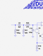
The input should have the standard DC blocking cap + the HF filter, like the circlophone, or any normal amp.
So say like in Circlophone: 330pF to the ground, 470Ohm in sequence to the input cap (say 4u7)
Any resistor to the ground after the input cap?
If so, what value? Circlo has 10k..
2.5V would be enoughAlso, as for voltage of caps:
C4/C5: 6.3V
35V is enoughC2/C3: 50V
Happy New Year!
For R25 - you mentioned that it can be used to adjust quiescent current.
So I guess I should use R25 (say 470 Ohm) + 1k trimmer?
Also - do you expect driver transistors to run hotter/cooler than Circlophone drivers?
Not sure how big heatsinks they will require..
For R25 - you mentioned that it can be used to adjust quiescent current.
So I guess I should use R25 (say 470 Ohm) + 1k trimmer?
Also - do you expect driver transistors to run hotter/cooler than Circlophone drivers?
Not sure how big heatsinks they will require..
Thanks!Happy New Year!
Yes, for a first build that would be reasonable.For R25 - you mentioned that it can be used to adjust quiescent current.
So I guess I should use R25 (say 470 Ohm) + 1k trimmer?
Hopefully, later versions could dispense with the adjustment, since it is one of the main design goals of current dumping amplifiers
Given the value of R1 and R2, they will run at the same temp as for a Circlophone (for comparable supply voltages)Also - do you expect driver transistors to run hotter/cooler than Circlophone drivers?
Not sure how big heatsinks they will require..
Here is a prototype of the PCB.
http://www.slowbears.com/tmp/pcb1.jpg
Would appreciate 2nd pair of eyes verifying it.
It's small and dense: 6cm x 7cm only.
If you have Sprint Layout software, I can email you the lay6 file...
http://www.slowbears.com/tmp/pcb1.jpg
Would appreciate 2nd pair of eyes verifying it.
It's small and dense: 6cm x 7cm only.
If you have Sprint Layout software, I can email you the lay6 file...
Nice and compact indeed.
I should have mentioned it earlier, but it would be preferable to have Q7 & Q8 in the thermal vicinity of the drivers, or OP, or both: a current dumping amplifier doesn't need a true thermal compensation like traditional AB amps, but if the temperatures drift really very far apart, it could begin to cause problems.
No need for a tight thermal coupling, but some proximity would be beneficial.
I realize that it would not be easy, and it is not a high priority, but if doable, it would be worthwhile.
Something else I forgot to mention: in its present form, the amplifier is completely DC-coupled. Some see it as an advantage, but in general people prefer AC coupling, because it keeps the output offset well under 10mV.
To make it AC-coupled, all that is needed is a 47µF or 100µF cap in series with R18; polarity is indifferent a it will never see more than a few mV, and the voltage can be as low as 2.5V.
Should be easy to implement if required
- Home
- Amplifiers
- Solid State
- EZ-Dump: dump your current without really trying