Thanks Valery for the response.
My plan is to use the Tubsumo OPS with some Slewmaster IPS i have. I read in previous posts how to poweron first the boards seperately.
The OPS should run at +/- 52 V , so 15kOhm between PDand V+, respectively PN and V-, results in a VAS current of about 3,5mA and leads to an Ugs of about 350 mV on each side. Can i go down to 6,8_7,5 kOhm to set the VAS current to about 7 to 8mA , to make the Lateral Fets conduct?
BR
Günni
Hi Günni - thank you for the explanation.
OK, standalone test makes sense - you can use the resistors to set the current through them being more or less close to the VAS current of Slewmaster IPS.
Set the bias trimmer to the lowest value position. In this case, voltage drop between the gates is set by the diode, which is not enough for opening, so you are safe.
As soon as you carefully rotate the trimmer, at some point you will see the voltage across the source resistors (0.1 ohms) - I normally measure across both source resistors in series - that gives slightly higher precision.
Please run this test with no load - exercise with resistors at the input may result in some DC offset at the output, which is no problem as far as the load is disconnected.
As soon as you connect the OPS to your Slewmaster IPS board, It makes sense to set the trimmer to low resistance and re-adjust the bias once again.
Cheers,
Valery
Hi Valery,
OPS works now, i am able to set the bias to the LATFETs to max. 130 mA, which should be enough (80-100mA is my chosen range) with a VAS current of about 7mA.. In case of less VAS current from the slewmaster IPS (4-5mA), will increase the R13 and / or R1 , since i have the TO-3p lateral Fets from Hitachi and Renesas and the replacements from Exicon, all with different threshold voltages for Ugs. I think 5 mA VAS current should be enough, as i dont wanna change the VAS resistor on the IPSs.
Thanks again and cheers
Günni
New TubSuMo
I am starting a TubSuMo build based on completed boards, heatsinks, and tubes from Evan (see post 662 Ultra-high performance, yet rather simple - hybrid and more!).
I’m planning on using SMPS to simplify things. This will include auxiliary voltage for the 12AU7 as well as power protections. If cost were not a consideration, I’d definitely go with 1 SMPS per channel in monoblocks, but I’m theorizing putting everything in one chassis.
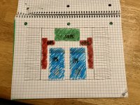
See my attached to-scale drawing. I’ve preliminarily surmised I can use the diyAudio store 244x240 base plate and heat sink brackets for a baseline structure. The heatsinks are 10x8x3 inches.
The smps drawing is based on the Connex SMPS500RXE. I think I can fit one bigger smps in that area, or two 300w in there stacked with riser board(s) from the store.
Evan has generously sent me his original monoblock enclosures, as well. I will likely use those for initial testing, but they are a bit larger than ideal.
Question time:
1) Is the Connex SMPS500RXE enough for stereo? SMPS500RxE | Connex Electronic
If not, would two SMPS300RE suffice? SMPS300RE | Connex Electronic
2) Would bias testing/setting be any different for 60vdc vs 70vdc?
3) How much current does the 12AU7 need?
4) Does my elementary school layout plan make sense?
Thanks for your insights!
I am starting a TubSuMo build based on completed boards, heatsinks, and tubes from Evan (see post 662 Ultra-high performance, yet rather simple - hybrid and more!).
I’m planning on using SMPS to simplify things. This will include auxiliary voltage for the 12AU7 as well as power protections. If cost were not a consideration, I’d definitely go with 1 SMPS per channel in monoblocks, but I’m theorizing putting everything in one chassis.
See my attached to-scale drawing.
I’ve preliminarily surmised I can use the diyAudio store 244x240 base plate and heat sink brackets for a baseline structure. The heatsinks are 10x8x3 inches.The smps drawing is based on the Connex SMPS500RXE. I think I can fit one bigger smps in that area, or two 300w in there stacked with riser board(s) from the store.
Evan has generously sent me his original monoblock enclosures, as well. I will likely use those for initial testing, but they are a bit larger than ideal.
Question time:
1) Is the Connex SMPS500RXE enough for stereo? SMPS500RxE | Connex Electronic
If not, would two SMPS300RE suffice? SMPS300RE | Connex Electronic
2) Would bias testing/setting be any different for 60vdc vs 70vdc?
3) How much current does the 12AU7 need?
4) Does my elementary school layout plan make sense?
Thanks for your insights!
Attachments
Hi Marc, all looks good. Evan's build is well-tested.
You will need 6.3V AC or DC for the tubes' filaments - both options are perfectly fine according to the data sheet. Each tube consumes 300mA - your aux voltage source must be powerful enough.
I like the configuration with two SMPS300RE PSU boards better - separate PSUs lead to lower crosstalk, it is also easier to avoid ground loops.
+/-60V will be no problem. bias setting - as usual. Start with lower bias, then adjust, let the thing warm up, adjust again.
Please keep me in the loop!
Cheers,
Valery
Thanks, Valery!
As luck would have it, I was able to purchase two SMPS500R +/-60vdc shipped from hifimediy in OR, USA for a negligible amount more than 2 SMPS300RE shipped from connexelectronics.
No problem with more available power.
The Aux output is rated at 500 mA, so that should suffice. I will need to regulate it down from ~15 to 6.3vdc.
This is exceptionally exciting. I’ll update this thread as the build progresses.
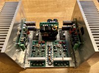
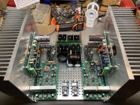
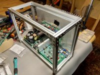
A bunch of goodies arrived today.
I couldn’t help but play around with some test fitments.
Still have some riser panels on the way for securing the SMPS.
I can envision also developing narrow and tall monoblocks, but I will have to step up the DIY with something like makerbeams...
I couldn’t help but play around with some test fitments.
Still have some riser panels on the way for securing the SMPS.
I can envision also developing narrow and tall monoblocks, but I will have to step up the DIY with something like makerbeams...
Attachments
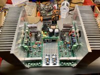
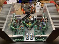
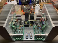
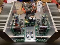
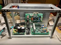
Tight spaces... Monoblock arrangement is getting more favorable. However, it’s still compelling to try to build all of this into a stout single chassis.
Though I liked the spacing of the previous post picture, it wouldn’t have given the SMPS enough room for cooling on the heatsinks.
Other options are in the pictures.
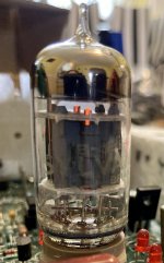
Also, I fired up one tube! Very exciting.
Though I liked the spacing of the previous post picture, it wouldn’t have given the SMPS enough room for cooling on the heatsinks.
Other options are in the pictures.
Also, I fired up one tube! Very exciting.
Attachments
-
 49FB2DD5-4666-4F48-B0AF-5588BD623B43.jpg357.3 KB · Views: 487
 -
 A9C29CA4-270C-46D8-A1D6-13441C9880D3.jpg1 MB · Views: 473
 -
 936BA6AE-EDD2-4873-8EFA-EB121258168F.jpg1 MB · Views: 464
 -
 09F232EC-8B1D-414E-BB69-5097C4F6FBDA.jpg1 MB · Views: 160
 -
 91BC3530-0F69-4570-ABC1-A92B73CE6A1E.jpg1,022.9 KB · Views: 143
 -
 491E00B6-9286-410F-953C-EA897096B551.jpg1,009 KB · Views: 164

Tight spaces... Monoblock arrangement is getting more favorable. However, it’s still compelling to try to build all of this into a stout single chassis.
Though I liked the spacing of the previous post picture, it wouldn’t have given the SMPS enough room for cooling on the heatsinks.
Other options are in the pictures.
Also, I fired up one tube! Very exciting.
Magic glow
As John Broskie says: "No glow - no go!" 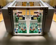
To be clear, that picture is just the one monoblock I built the structure for, mirrored and added as a second image for an *imagined* stereo amp. I’ve yet to wire everything up and test the prototype. Eventually, I expect to have the two built and tested in a quasi-mirrored arrangement. Some additional brackets could meld them together for the Hyper TubSuMo Megazord.
With your woodworking skills, Evan, I would have done the same thing. I’m going out of my way to put these together with zero drilling, tapping, or cutting of aluminum. I don’t have the machining chops. Polycarbonate panels are likely going to go into the slots of the makerbeams. This project is too interesting to close up out of sight.
The SMPS absolutely cut down on space and weight. I’ve been interested in trying them out with a strong class AB amp for a while.
The SMPS absolutely cut down on space and weight. I’ve been interested in trying them out with a strong class AB amp for a while.
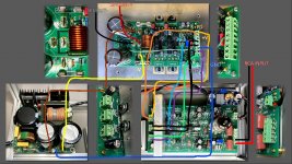
Valery and others familiar with this amp, can you please review my wiring drawing? I have reasoned out the obvious connections between the boards. Does neutral from the power supply connect to the OPS next to 'GND2' in one of the open terminals there?
What's not shown here is xrk's SSR speaker protection board I will connect to the speaker output. Ready-to-Run (RTR) SSR DC Speaker Protection and Delay GB
I believe that should keep the output disconnected from the speakers until the 12AU7 is warmed up.
Thanks!
What's not shown here is xrk's SSR speaker protection board I will connect to the speaker output. Ready-to-Run (RTR) SSR DC Speaker Protection and Delay GB
I believe that should keep the output disconnected from the speakers until the 12AU7 is warmed up.
Thanks!
Attachments
Last edited:
- Home
- Amplifiers
- Solid State
- Ultra-high performance, yet rather simple - hybrid and more!