I possibly made 100 + of these , they were used as an industrial amp. For a bet I made a hi fi version. I was astonished.
The transistors Maplin supplied were of the very highest grade. Ones I bought to make clones were less good. I bought the last 55 GA28F's and all the 2SA872A's they had. So sad they stopped doing the PCB. I never had one give a problem on start up. Not one fell out of spec. I suspect I made 40 clones with additional current source to replace R3 47 K.
The caps I like best are these. Not Audiophile , not high temperature.
MAL205018103E3 - VISHAY BC COMPONENTS - CAP, ALU ELEC, 10000UF, 63V, SOLDER | Farnell UK
ALT22A103CD063 - BHC COMPONENTS - CAP, ALU ELEC, 10000UF, 63V, SOLDER | Farnell UK
Last edited:
I saw some 1 mA of these at a silly price on eBay ( 1 mA to relpace R3 )
Current Limiting Diode CRD 2.0mA | Rapid Online
I suspect if the resistors R4/5 were 2K and C 5/6 47 pF these cheaper 2 mA versions would work. DC offset work double to an acceptable 40 mV at a guess ( Rotel RA 931 82 mV ). One might add 2 x 24R between the emitters of TR1/2. This is a problem that is explained by Rod Elliot in many amps he designed. Double the current and double the problems. Like a dog chasing it's tail you seldom win as much as you hope. At the point of winning the amplifier might become unstable into a real load. Hitachi knew best.
These would drop in without any modifications. Personally I wouldn't bother at this price.
4 X Semitec E102 E 102 1mA CRD Current Regulative Diode | eBay
One other way is to fit 2 mA version and bleed 1 mA to -VE ( 47 K ). Never tried it , should work. Might cause hum.
Last edited:
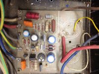
Here is my version of the Maplin mosfet amplifier.
Changed output transistors vertical mosfets.
Added source resistors.
Added Vbe multiplier.
Sounds great.
Added decoupling (RC) to LTP and VAS stages to make it hum free with no signal.
Changed output transistors vertical mosfets.
Added source resistors.
Added Vbe multiplier.
Sounds great.
Added decoupling (RC) to LTP and VAS stages to make it hum free with no signal.
An externally hosted image should be here but it was not working when we last tested it.
Last edited:
Like the RS box, looks like my shed. I am told standard FET's can fail in similar fashion to bipolar. The distortion residuals are likely to include a few higher order things. I had some running at 200 watts, suddenly they let go. I had chosen 200 V ( P) and 500 V types of similar Ron in TO247.
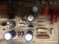
Here are my clones. D Self recommends a separate return path for the Zobel C7 R15. Didn't work for me. The metal bar restores it to Maplin style. See ground to decouplers. Some of these PCB's were made mirror image by mistake. These were the proper ones I think? The wording on the bottom is the only way they could do it from my old photographic PCB files. Note 10K discharge resistor to each rail and slightly nicer output take off point. No point really as Ron moves the centre point.

Here are my clones. D Self recommends a separate return path for the Zobel C7 R15. Didn't work for me. The metal bar restores it to Maplin style. See ground to decouplers. Some of these PCB's were made mirror image by mistake. These were the proper ones I think? The wording on the bottom is the only way they could do it from my old photographic PCB files. Note 10K discharge resistor to each rail and slightly nicer output take off point. No point really as Ron moves the centre point.
Someone has beaten you to it !
50 watts RMS audio power amplifier module hi fi home guitar | eBay
50 watts RMS audio power amplifier module hi fi home guitar | eBay
Hi
The alternative kit is great .. but just thought a original version in 2 oz copper tracks would be a good alternative .. I have the original transistors as well with new passive components, for some reason with all the module short comings I have found the unit a pleasure to make, very reliable and sound very good with a big power supply .. unlike most of the Chinese I pod thingies full of chips and service mount stuff etc.
A good little hobbyist amp .. and can be bridged ... if you stick to a monoblock version the 50 Hz hum is not that bad
regards
Nick
2oz is not really required. Better do 2 sided. Take power directly to the output devices is better and very easy. 2 oz sometimes gives dry joints if not too careful. 2 oz is less inportant with FET's as Ron on is very high anyway. A 3 mm track being vastly lower resistance. The one thing I did on my PCB although doubtful of need is make the source output take off to the device centres.
The CCS is an option. My own tests suggest not really needed ( R2 47 K is it ? ) . The Zobel grounding green bar is 1.2mm copper. I think it works better this way. I take the return between the 220 uF decouplers ( high grade if possible ) . If the Zobel 4R7 0.1uF is taken to PSU ground you might get problems. Maplin take it to the input. Maybe they found it better? No Zobel problems their way. Text books advise against their way.There is a big capacitor near the input on mine. That's for something I did. The pink reistors for emitter degeneation if wanted. As the Maplin current is 500 uA per device 0R will be fine as they did. If you change the CCS to 330R you might change Re to 2 x 24R. The problem with that is the VAS resitors need to be 1K8 ( 3K9 @ 2 V usually ) and cVAS perhaps 2 x 47 pF ( 27 pF) . So what was gained has to be made safer and DC offset greater. Did that win anything?The 20 to 35 V per uS is fine for this design. A BCV 61 SMD double current mirror could be fitted on the PCB. Have some extra holes if so to jump it into Maplin use. If the BCV was provided for the amplifer it could become a very high slew device. Personally it is fine as it is. My real doubt is todays transistors. 2N5551/5401 do not have the very high gain of 2SD756 and 2SB716. In fact MPSA 42/92 perhaps a bctter choice ( lower Cob I think ) . If so having a BCV61 would help pump extra current. In my eyes slewing is only that. If you try to feed a transistor that is sitting at a very low input resistance a high resitance feed will not help ( 1965 thought it different and said transconductance, TID was then discovered ). For the want of very little PCB space between 2 x 3K9 the BCV61 seems worthwhile. Do not use two transitors. It never gives as good a match. The 20 V spec is no problem as the VAS ( 2 x 2SD756 ) clamps it at 2 V. That is the problem . The Vce of the BCV 61 is ideal and matched via common chip. Alas BCV 60 can not do the VAS current mirror as it needs to be a 120 V device.

The CCS is an option. My own tests suggest not really needed ( R2 47 K is it ? ) . The Zobel grounding green bar is 1.2mm copper. I think it works better this way. I take the return between the 220 uF decouplers ( high grade if possible ) . If the Zobel 4R7 0.1uF is taken to PSU ground you might get problems. Maplin take it to the input. Maybe they found it better? No Zobel problems their way. Text books advise against their way.There is a big capacitor near the input on mine. That's for something I did. The pink reistors for emitter degeneation if wanted. As the Maplin current is 500 uA per device 0R will be fine as they did. If you change the CCS to 330R you might change Re to 2 x 24R. The problem with that is the VAS resitors need to be 1K8 ( 3K9 @ 2 V usually ) and cVAS perhaps 2 x 47 pF ( 27 pF) . So what was gained has to be made safer and DC offset greater. Did that win anything?The 20 to 35 V per uS is fine for this design. A BCV 61 SMD double current mirror could be fitted on the PCB. Have some extra holes if so to jump it into Maplin use. If the BCV was provided for the amplifer it could become a very high slew device. Personally it is fine as it is. My real doubt is todays transistors. 2N5551/5401 do not have the very high gain of 2SD756 and 2SB716. In fact MPSA 42/92 perhaps a bctter choice ( lower Cob I think ) . If so having a BCV61 would help pump extra current. In my eyes slewing is only that. If you try to feed a transistor that is sitting at a very low input resistance a high resitance feed will not help ( 1965 thought it different and said transconductance, TID was then discovered ). For the want of very little PCB space between 2 x 3K9 the BCV61 seems worthwhile. Do not use two transitors. It never gives as good a match. The 20 V spec is no problem as the VAS ( 2 x 2SD756 ) clamps it at 2 V. That is the problem . The Vce of the BCV 61 is ideal and matched via common chip. Alas BCV 60 can not do the VAS current mirror as it needs to be a 120 V device.
BTW # 50. You can see a PCB brake on what would be the Maplin power rails to outputs. This was for extra PSU or filtering. Turquiose 33K feedback, white near diode 1K feedback lower arm ( make upper 47 K if you like to suit passive preamp or use with Quad 33/34/44 ). Blue 100R. Crosshatch 2W 12K. Gold 3K9. Orange outline 0.1uF. Choke 16 x 8mm ID 10 mm OD 1mm wire. Black crosshatch 4R7 3W. CCS is not complete on this drawing. On the real one I have a small rail cutout to allow the 2 x 1N4148 jump to the transitor and the 47K where the dotted lines reisistor is. Sorry to say the real one is lost after a computer disaster. This one is 90%. If you look the 2 x gold 3k9 have room for a BCV61.
Another Hitachi App note clone
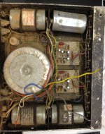
Some years ago I bought off the local auction site a Perreaux E2/2000 pcb, power transformer and schematic. I built a suitable chassis using heatsinks recovered from scrapped inverter welders and scrap al plate over xmas 2014. This xmas I finished populating the pcb, matched the fets into sets, assembled it, powered it, set the bias (330mA), ran it into a dummy load, 311w/8R per chan. Stability checks ok. I used BF469/70 in the VAS instead of MPSA42/92. Listened to music through it this afternoon.
Some years ago I bought off the local auction site a Perreaux E2/2000 pcb, power transformer and schematic. I built a suitable chassis using heatsinks recovered from scrapped inverter welders and scrap al plate over xmas 2014. This xmas I finished populating the pcb, matched the fets into sets, assembled it, powered it, set the bias (330mA), ran it into a dummy load, 311w/8R per chan. Stability checks ok. I used BF469/70 in the VAS instead of MPSA42/92. Listened to music through it this afternoon.
BF720/721 I suspect are similar , again a SMD foot print inside TO92 could help. What seems to be said with these is they are more linear. I suspect in reality linearity in a MOS FET amplifier is loop feedback and nothing else. I would suggest these are the only amps in the world that thrive on loop feedback. I have built some with unity gain without any problems on tag strip ( sub woofer with big EQ, unity as starting point as the amp was the filter ) The connection with valves is tenuous. However there are mysteries as this amp sounds far better than it should. Guess what, it measures far better than it should. HH 1200 used MPSA42/92. 2N5551/5401 is the middle ground between MPSA42/92 and 2SD756/1SB716. Profussion who sell Exicon FET's also sell some transistor that might work. One set in TO126. If the holes enlarged collector should be centre as with the prefered devices ( ECB on the written side ).
BD139/140 can be used. Make rails +- 35 V off load max ( at 253 V/130V ) . Tail resistor ( R2 ? ) 33 K and add 18 K in paralell to 12 K 2W into ( 10 nF instead of 6n8 ? ). The inputs BC560C if so ( pin out different ). If a double set of outputs used my Magneplanars would like this amp. I would double the tail current ( 15 K ) and change 2 x 3K9 to 2 x 1K8. The VAS caps 47 pF NPO. 500 VA 0-25 0-25 . If the PCB split as mine the driver stage could be regulated to ensure safety. Having the driver clip first is no bad thing if a music lover. Safety can be a simple RC fitler as the input/driver stage will be about 15 mA constant this way. 330R + 1000 uF looks to be OK ( trim R later ). If DC offset is below 50 mV to me that would be OK. I made the cap spaces larger than the Maplin to allow fitting non polar caps on my PCB. Tests show them to be better. BD 139/140 will have higher Cob etc . If so it might be possible to reduce the VAS cap . The mystery as to how low Cob is required in the Hitachi design when set against the 1 nF gate capcitance was solved by Bob Cordell. That capacitance is bootstrapped by the load. The one of greater note is Cgd which never is talked about. Thus low Cob is needed. The craziest thing people say is the MOS FET sound is the Cg. This is nonsense as the fullpower bandwidth is about 30 kHz without any trouble. The distortion at 50 kHz is almost as good as 20 kHz. It doesn't take a rocket scientist to see 7 mA will not drive 1 nF at 30 kHz if not so ( to be clear it has enough ). As far as I know the Cgd is the one that does matter. The next crazy thing they say is fit a buffer. What they really mean is change the FET into a bipolar amp and then fit bipolars. Crazy. The facts speak for themselves. Also the amp doesn't need high slew rates as the loop can close. This is becuase the output stage is vastly faster than a 50 MHz bipolar as the 50 MHz is never realised in practice due to the device needing current. When slew limiting happens on a bipolar amp the crossover distortion is seen on the upper sections of the wave. This is the feedback failing. Often this is done because to them music is a 200 kHz thing. Crazy thing is this amp is a 200 kHz amp if you ask it nicely.
BD139/140 can be used. Make rails +- 35 V off load max ( at 253 V/130V ) . Tail resistor ( R2 ? ) 33 K and add 18 K in paralell to 12 K 2W into ( 10 nF instead of 6n8 ? ). The inputs BC560C if so ( pin out different ). If a double set of outputs used my Magneplanars would like this amp. I would double the tail current ( 15 K ) and change 2 x 3K9 to 2 x 1K8. The VAS caps 47 pF NPO. 500 VA 0-25 0-25 . If the PCB split as mine the driver stage could be regulated to ensure safety. Having the driver clip first is no bad thing if a music lover. Safety can be a simple RC fitler as the input/driver stage will be about 15 mA constant this way. 330R + 1000 uF looks to be OK ( trim R later ). If DC offset is below 50 mV to me that would be OK. I made the cap spaces larger than the Maplin to allow fitting non polar caps on my PCB. Tests show them to be better. BD 139/140 will have higher Cob etc . If so it might be possible to reduce the VAS cap . The mystery as to how low Cob is required in the Hitachi design when set against the 1 nF gate capcitance was solved by Bob Cordell. That capacitance is bootstrapped by the load. The one of greater note is Cgd which never is talked about. Thus low Cob is needed. The craziest thing people say is the MOS FET sound is the Cg. This is nonsense as the fullpower bandwidth is about 30 kHz without any trouble. The distortion at 50 kHz is almost as good as 20 kHz. It doesn't take a rocket scientist to see 7 mA will not drive 1 nF at 30 kHz if not so ( to be clear it has enough ). As far as I know the Cgd is the one that does matter. The next crazy thing they say is fit a buffer. What they really mean is change the FET into a bipolar amp and then fit bipolars. Crazy. The facts speak for themselves. Also the amp doesn't need high slew rates as the loop can close. This is becuase the output stage is vastly faster than a 50 MHz bipolar as the 50 MHz is never realised in practice due to the device needing current. When slew limiting happens on a bipolar amp the crossover distortion is seen on the upper sections of the wave. This is the feedback failing. Often this is done because to them music is a 200 kHz thing. Crazy thing is this amp is a 200 kHz amp if you ask it nicely.
2SA1209 SANYO -160V -0.14A 200 10W 150MHz TO126 PNP
2SC2911 SANYO 160V 0.14A 200 10W 150MHz TO126 NPN
Medium Power-Driver
These seeem ideal. If the holes of the latter transitors are made larger these will fit ( TR3,4,5 ).
Whilst still possible these.
Buy Bipolar Transistors 2SA1085E PNP Bipolar Transistor, -100 mA -120 V HFE:400 V 90 MHz, 3-Pin TO-92 Renesas Electronics 2SA1085E online from RS for next day delivery.
Buy Bipolar Transistors 2SA970BL PNP Bipolar Transistor, 0.1 A 120 V HFE:200 V 100 MHz, 3-Pin TO-92 Magnatec 2SA970BL online from RS for next day delivery.
Lateral Mosfet
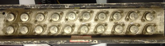
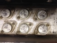
I have one of the 8 device heatsinks from Nigel C. 10 would be better , very jealous. It would be worth making thoese amps tidy as his ideas were very good. I borrowed a GEC valve book from Nigel and saw one of his amps. Carnhill made the transformers I seem to remember? Nigel had a Triumph Bonneville brand new. Inside a few years it looked like the amps.
Nigel said feeding a 9 V battery into the feedback loop made it sound better. I never did get to understand that. Nigel also said the more FET's added the better the sound. This is good to know as most think otherwise. Bob Cordell said why. It takes a genius like Bob to say what my ears heard when others say don't bother.
I went to clear Nigel's workshop some years agao. I gave him a few pounds. When leaving he asked me would I want a pedestal drill for nothing? It is a Seallly and would cost about £250. What a very nice man he was. He was by his own understanding Autistic. He found using my name difficult and would stumble. We all miss him.
I suspect you will find the drivers are BF469/70 as I have a big bag of them from Mr C. Nigel said he tried to build a version of his big amp and failed. This was to exactly the same layout as always. I think this was to him nature saying move on. Nigel changed an Exposure amp to this design. Some little things were wrong which was nothing to do with him. I sorted it out and must say it was supurb. I had to change R2 and tweek the 12 K 2 W. The chap who owns it is PHD in related subjects and a professional opera singer. He loves it. His BSc was in current dumping amplifers so a compliment to Mr C.
More power captain !
It looks like there was a stopper on each gate.
What about a power sharing resistor?
Were the drivers changed from the standard Maplin?
Andy
No need for power sharing as the Ron takes care of that. Exicon sell in matched gate voltage to get a good overal match. Mr C has the right idea. The typical 100 R is bought for it's inducance as much as anything ( I use 220R ), high grade would be a bad idea. I was stupid enough to measure the gate, D Self advises that should lunch the device. I saw a nice 5 MHz sinewave. It seems not enter the VAS when gate stopper in place. The ferrite hoop will possibly do a better job.
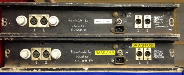
I think the drivers are possibly BF 469/470 as I was given a big bag by Huxter himself. Personally speaking that is not a good move as the very high gain of the Hitachi devices was part of some great magic.
I think the drivers are possibly BF 469/470 as I was given a big bag by Huxter himself. Personally speaking that is not a good move as the very high gain of the Hitachi devices was part of some great magic.
Last edited:
- Home
- Amplifiers
- Solid State
- Maplin MosFET Amplifier Ga28f construction thread