Phew, thank god for that. For a moment there I thought there was nothing wrong with it!
It's lovely and clean (okay, a good thick layer of dust, but that blew out with compressed air and a brush leaving it looking quite nice). I can't see any evidence of rework at all, which is nice - looks to have all its original components (even fuses!).
Both outputs are <10mV offset straight off, so I threw a sine wave in and looked with the CRO (no load). Lovely output on both channels, with no sign of clipping until I hit the ~70V rails.
Looking with more detail (spec-an) I've got harmonics suppressed ~90dB (10V out) on the right channel, but only ~40dB on the left. I suspected there might be something wrong with the soft clipping circuit, so tried turning soft clipping on and off. Interestingly the distortion disappears for thirty seconds or so after I switch the soft clipping switch off, but then returns.
I'll go have a good look at schematics, but my guess is that it's a leaky cap between pre-out and power amp in, much as what was causing the mute issues on my other one.
That was a straightforward fix. I went probing around the soft clipping circuitry on each side, and found the +ve supply for the left channel soft-clip was 0V rather than 11 for the right channel, and -11 for the -ve supplies on each channel.
I initially figured C413 had gone closed circuit, so swapped it out, but no joy. Turns out R423 was open circuit. Absolutely no signs of anything amiss visually, but tested >1M out of circuit.
So swapped in a replacement and now both channels have distortion products lower than -90dB at 40V RMS out.
Sounds quite nice, though the hum level is a tad higher than my other one, where I replaced all the caps. I'll go ahead and replace all the caps on this one too, but there's obviously a bit to order there.
Attachments
I have been working with the PE series at NAD for about 20 years and they always fail in a strange and original way.
thank you for this information, I will classify for later, when I would like to work on my 3240.
I also have some Proton who are very close and who also fail in a strange and surprising way.
thank you for this information, I will classify for later, when I would like to work on my 3240.
I also have some Proton who are very close and who also fail in a strange and surprising way.
I've been following this thread with great interest - I've got a sick 3240 on the workbench, but I can't seem to lick the problem I'm seeing.
Firstly there's 32 volts at the speaker terminals in the right channel - I can't see any obvious issues with the output transistors as they seem to test fine out of circuit. It originally had a blown bridge rectifier on the 42 volt rail supply and a blown 68 ohm resistor R466 (and a blown fuse).
Can anyone who knows anything about the circuit in the 3240 shed some light on the problem?
Before you do anything else, check C416. If the output had +32 V on it, this part (a 10 V electrolytic) is very likely toast. The 2SC2240s and 2SA970s are rated 120 V C-E, they probably would still just about hold up even if subjected to full rail voltage (up to 140 V).
Another common kind of defect would be the feedback resistor, R470, 18k 1/2 W. If that is bad, DC offset would skyrocket. Linearity for this part is rather important, so it should be a metal film.
Check all of Q403/404 and 407/408. It's often the ones on the feedback side that suffer damage. If any of them have to be replaced, note that you must do so in pairs (i.e. 403+404 or 407+408). The transistor pairs should also be thermally bonded (using epoxy, wire or whatever else may already be there).
I'm just starting to check out a 3240PE as well.
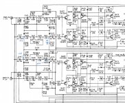
It looks like there is a schematic discrepancy between the images at the start of this thread posted by BentMike and the images in the NAD-3240PE-int-sm.pdf service manual that is on-line.
R466 is shown in the service manual schematic as feeding Q420 collector as well. My pcb follows this schematic (not BentMike's), so I'd also check Q420 and Q424.
Ciao, Tim
Yes they were.
Q403, Q404, and their mating pairs Q407 and Q408 all tested fine out of circuit.
I've been thinking though - I haven;t had much time to do troubleshooting on this but if there is an offset of +36V or so would that mean that either the positive rail is conducting 72V rather than the 43V while the negative rail is normal?
Or could it be that the negative rail isn't conducting at all.
I'm sure a multimeter probe would provide the answer to these questions, but I was just thinking to myself...
R466 is 68 ohm and about 0.6W rated, and raised above the pcb, so they obviously realised it could burn out for some types of fault. 3W dissipation would be about 200mA.
A quick look indicates 200mA could flow if Q404 had a collector-base short and the speaker line was sitting at -70V. Or if Q412 had a collector-base short. The output at 32V could be related to a bad Q424. But perhaps best to check specific sections of circuitry for ok operation.
Perhaps if you just had the 70V rail fuses in (43V and 20V rail fuses out), and lifted a leg of the PTC1/2, then the main amp input circuitry could be checked for appropriate dc levels. Perhaps that could also initially be tested with Q420/422 collector and D418/420 legs lifted to isolate the main amp output circuitry.
Another test could be with just the 43V rail fuses in. With R472 exposed, the output stage could be checked for a bad part.
It sounds like you don't have a variac to lessen the impact of a bad part causing stress on other parts. Another way to reduce stress while fault-finding is to replace a pair of fuses with a pair of resistors.
I might be a bit closer to the problem.
I found a bad biasing resistor R472 which had gone open circuit (the solder bridge across it was removed for testing a while ago) and the right channel offset went from 32 V to 47 V.
Makes me wonder if there's something going on around Q432 and Q436...
Didn't have much time to poke at it today, but perhaps tomorrow.
I just use a variac, and only put relevant fuses (and PTCs) in place to confirm all transistors are operating with appropriate Vbe and Vce levels in a particular circuit section at a time - saves any stress/pops from just applying full mains.
That made it relatively easy to find bad Q428 2SD1047 and Q430 2SB817, and then bad Q432 and Q434, having visually spotted bad PTC1,2 and C505 at the start (the PTC's appear to have got hammered after transistors started filing, and appear to have stressed out a 43V rail filter cap to the point of venting as it likely got supplied from the 71V rails).
I'm waiting on some parts to finish the bad channel I have, but noticed that the bias current pot is very twitchy, even after cleaning, and I pretty much have to resort to taking a resistance measurement across the pot as a means to then make an incremental adjustment, and that is after paralleling 1k2 across the trimpot to reduce sensitivity for the resistance I need to target.
I'm leaving a full electrolytic recap until I can confirm nominal operation, and so have just used smaller temporary caps for the main filter caps to get me through initial testing.
Just starting on a 7240PE now - it is an earlier version of main pcb, with slight differences in layout.
Last edited:
- Home
- Amplifiers
- Solid State
- DIY includes repair? NAD 3240PE advice needed...