It does not always start out as a happy story. Strange Forest of Noise with Linear PSU
4 way Active crossover ==Ground loop noise
Hello Folks ,
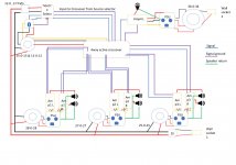
Just finished my 4 way active project . When I tested individual amps( two p3As and 4 Elvee'Circlophones and single LJM150D ) they all performed really well. But when I connected all of them to 4 way active crossover, there is ground loop noise . can anyone suggest me better way to wire them all.
I went through various thread and gathered many information. I am seeking advice before implementing any changes.
Thanks in advance for your help.
-Goutham
Hello Folks ,
Just finished my 4 way active project . When I tested individual amps( two p3As and 4 Elvee'Circlophones and single LJM150D ) they all performed really well. But when I connected all of them to 4 way active crossover, there is ground loop noise . can anyone suggest me better way to wire them all.
I went through various thread and gathered many information. I am seeking advice before implementing any changes.
Thanks in advance for your help.
-Goutham
Attachments
Thanks for your note Scottjoplin. I understand there are multiple potential loop.
So far I have tried one option : I disconnected all 3 signal ground to the right
channel from active crossover board . but the problem still persist.
Next I want to try connecting all PSU ground to 1 star point and disconnect all signal ground from crossover board (Except Amp4= which is a subwoofer amp and located in a completely different enclosure). do you think that is good idea ?
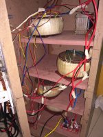
With respect to physical layout : 6 amps (2of P3A and 4 of Circlophone ) are in same enclosure along with active crossover , source selector and bluetooth receiver . Amp4L(Subwoofer amp) and its PSU and 36-0-36 transformers are in another enclosure.
Both amplifiers and crossover exhibits no symptom of noise when tested individually .
So far I have tried one option : I disconnected all 3 signal ground to the right
channel from active crossover board . but the problem still persist.
Next I want to try connecting all PSU ground to 1 star point and disconnect all signal ground from crossover board (Except Amp4= which is a subwoofer amp and located in a completely different enclosure). do you think that is good idea ?
With respect to physical layout : 6 amps (2of P3A and 4 of Circlophone ) are in same enclosure along with active crossover , source selector and bluetooth receiver . Amp4L(Subwoofer amp) and its PSU and 36-0-36 transformers are in another enclosure.
Both amplifiers and crossover exhibits no symptom of noise when tested individually .
Hi. There are plenty of potential loops there through the signal wires, it depends largely on what is inside the loops, therefore the actual physical layout is important. You may still have to cheat")
Last edited:
Since this is still under test , have not connected it to chassis anywhere (I understand the electric hazard , but will soon make an arrangement)
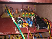
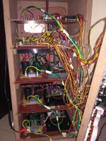
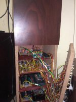
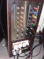
One more thing is, its all inside wooden speaker enclosure of 48 inches tall, 11 inches wide, 11 inches deep. Half of the enclosure (24 inches ) is been used for 3 drivers and remaining half if used for amplifiers, active crossover , source selector and bluetooth. Need to figure out a way to implement safety .
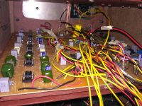
Each amplifier is attached to 2mm metal plate which will slide inside the enclosure like a rack server .
Will upload the photos soon.
One more thing is, its all inside wooden speaker enclosure of 48 inches tall, 11 inches wide, 11 inches deep. Half of the enclosure (24 inches ) is been used for 3 drivers and remaining half if used for amplifiers, active crossover , source selector and bluetooth. Need to figure out a way to implement safety .
Each amplifier is attached to 2mm metal plate which will slide inside the enclosure like a rack server .
Will upload the photos soon.
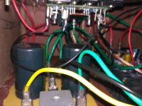
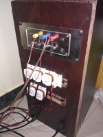
Photos of the setup. I will arrange the cable properly with a cable tie. I thought of doing it after testing it.
Haven't tried shorting the input. Will try it on this weekend. Meantime have also ordered 600:600ohms audio transformers from aliexpress. It was dirt cheap. Thought of trying it. It will take more than a month to receive them.
10pcs Red Nickel Alloy Audio Transformers 600:600 Ohm Europe 1:1 EI14 High Efficiency Isolation Transformers
10pcs Red Nickel Alloy Audio Transformers 600:600 Ohm Europe 1:1 EI14 High Efficiency Isolation Transformers-in Transformers from Home Improvement on Aliexpress.com | Alibaba Group
Attachments
-
 IMG_20181030_225859.jpg756.1 KB · Views: 161
 -
 IMG_20181030_225940.jpg750 KB · Views: 149
 -
 IMG_20181030_230010.jpg596.8 KB · Views: 148
 -
 IMG_20181030_230110.jpg605.2 KB · Views: 140
 -
 IMG_20181030_230139.jpg435.2 KB · Views: 134
 -
 IMG_20181030_230627.jpg423 KB · Views: 80
 -
 IMG_20181030_231042.jpg524.4 KB · Views: 95
 -
 IMG_20181030_231340.jpg335.2 KB · Views: 81
Last edited:
Thank you very much for your time and patience Scottjoplin. I am bit new to these and no engineer either . I think I am using screened cable. It has 3 conductors. 2 Insulated with different color plastic and third strands of aluminum surrounding these 2 insulated conductors. I am not using surrounding aluminum for anything .Just short the main input. Ideally the inputs should use screened cable, you may possibly get away with them being tightly twisted. All speaker pairs and power cables should be tightly twisted.
Will try everything you prescribed and report back. Once again thank you for your time.
On side note, do you think those 1:1 Transformer I mentioned above is any good for isolating all the inputs ?
Last edited:
Yes, that's screened twisted pair (STP), how are you connecting the conductors and screen? You should be using coax, one internal conductor for signal flow and screen for signal return (signal ground). You can isolate the inputs with transformers, but it shouldn't be necessary. It's a very ambitious project for somebody new to it
I am being stupid here
. Connected one wire to signal and other to signal ground . Completely cutting off the screen . Will change the cables to coax on next iteration. About 1:1 Audio trafo, I thought it is simple to wire them up. Use one side (Primary) for source output and other side (Secondary) for Amp input . Since the core is made of Nickle alloy , it should have very minimal losses. I saw some youtube videos on the identical trafo, and it showed flat frequency curve with the exception of slight dip at low frequency department . Anyways I am not going to use trafo for Subwoofer input(Remaining 3 channels will be isolated) .
My Crossover frequency is 70Hz -1700Hz-5300Hz
Last edited:
such short unbalanced connections shouldn't need transformers, unless best practices on cabling didn't work, which would be odd if your other equiment are silent (at home).
Have you read Rane notes? Sound System Interconnection
A book to recommend, worth every penny Henry w Ott - Noise Reduction Techniques in Electronic Systems
If you got screened twisted pair cable, connect the screen to the chassis ground on one end. Do not connect the shield to a signal ground.
The cable shield now acts as an extension to the chassis, which protects electronics inside from the outside environment electromagnetic fields.
The cable shield picks up stray electromagnetic fields from the environment inside the chassis and prevents them to get induced into the cables within the shield.
Error current picked by the cable shield is now effectively flowing to the chassis and to mains ground (when you have the mains ground connected to chassis ground, which you should), and not to signal or signal ground.
No comment on the overall system wiring and ground connections.
Have you read Rane notes? Sound System Interconnection
A book to recommend, worth every penny
Henry w Ott - Noise Reduction Techniques in Electronic SystemsIf you got screened twisted pair cable, connect the screen to the chassis ground on one end. Do not connect the shield to a signal ground.
The cable shield now acts as an extension to the chassis, which protects electronics inside from the outside environment electromagnetic fields.
The cable shield picks up stray electromagnetic fields from the environment inside the chassis and prevents them to get induced into the cables within the shield.
Error current picked by the cable shield is now effectively flowing to the chassis and to mains ground (when you have the mains ground connected to chassis ground, which you should), and not to signal or signal ground.
No comment on the overall system wiring and ground connections.
Last edited:
such short unbalanced connections shouldn't need transformers, unless best practices on cabling didn't work, which would be odd if your other equiment are silent (at home).
Have you read Rane notes? Sound System Interconnection
A book to recommend, worth every penny
If you got screened twisted pair cable, connect the screen to the chassis ground on one end. Do not connect the shield to a signal ground.
The cable shield now acts as an extension to the chassis, which protects electronics inside from the outside environment electromagnetic fields.
The cable shield picks up stray electromagnetic fields from the environment inside the chassis and prevents them to get induced into the cables within the shield.
Error current picked by the cable shield is now effectively flowing to the chassis and to mains ground (when you have the mains ground connected to chassis ground, which you should), and not to signal or signal ground.
No comment on the overall system wiring and ground connections.
Thanks for very useful information tmuikku.
Question regarding safety ground in a wooden enclosure like mine. I am planning to connect all the 0V line from PSU to star point and then connect it to ground socket of mains. I need to implement loop breaker circuit in this scenario . I am thinking of 3 alternatives :-
1 )loop breaker (Bridge rectifier , resistor and a capacitor )circuit for each PSU 0V where they join star point .(This, I think will work)
2) only one loop breaker where star point connects to ground terminal of wall socket.
3) Both option 1 &2 .
Which one you guys recommend ? since it is multi channel/ multiple transformer I know it is very complex.(I think I bit off more than I could chew
 )
)Thanks for your help.
You may find this interesting Cable shield as a Faraday cageIf you got screened twisted pair cable, connect the screen to the chassis ground on one end. Do not connect the shield to a signal ground.
The cable shield now acts as an extension to the chassis, which protects electronics inside from the outside environment electromagnetic fields.
The cable shield picks up stray electromagnetic fields from the environment inside the chassis and prevents them to get induced into the cables within the shield.
Error current picked by the cable shield is now effectively flowing to the chassis and to mains ground (when you have the mains ground connected to chassis ground, which you should), and not to signal or signal ground.
This would be best.1 )loop breaker (Bridge rectifier , resistor and a capacitor )circuit for each PSU 0V where they join star point .(This, I think will work)
It's possible to have similar problems with a stereo amp, monoblocks solve the problem of cross channel ground loops because they have separate supplies
- Status
- This old topic is closed. If you want to reopen this topic, contact a moderator using the "Report Post" button.
- Home
- Amplifiers
- Solid State
- Multichannel amplifier internal ground loop