[Solved...last page!]-Multichannel amplifier internal ground loop
Hello
I just finished a 6 channels power amplifier few days ago.
I have a Internal ground loop problem I guess.
I made a test using a generator on each individual channels and they all exhibit excellent noise figure.
But if I connect all six inputs together to the same generator there is a very bad totally unacceptable hum/buzz!
Even with all inputs not connected or even all inputs shorted on six channels, the noise remains.
I tried with 16 ohms resistors between all individual input cable shields and input grounds...no improvement.
And even with 110 ohms resistors no improvement at all.
Any hint to help me someone...?
Thanks
Luke
Last edited:
Yep, that's a classic case of a grounding interaction. You need to consider each and every conductor and what currents can flow and how they may interact with other parts of the circuitry.
This may you understand the problem (read all the thread around this post),
http://www.diyaudio.com/forums/soli...-lin-topology-nfb-tappings-2.html#post1624677
This may you understand the problem (read all the thread around this post),
http://www.diyaudio.com/forums/soli...-lin-topology-nfb-tappings-2.html#post1624677
Probably a poorly implemented input stage.
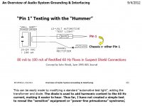
Start at page 101, the troubleshooting section of this Bill Whitlock paper:
"An Overview of Audio System Grounding and Interfacing"
by
Bill Whitlock, President
Jensen Transformers, Inc.
Life Fellow, Audio Engineering Society
Life Senior Member, Institute of Electrical & Electronic Engineers
http://centralindianaaes.files.wordpress.com/2012/09/indy-aes-2012-seminar-w-notes-v1-0.pdf
******************************
Also build a John Windt "Hummer" (instructions for use in the above paper)
Attachments
Last edited:
did you solve this???
if not post a schem of the amp
No...not yet, actually.
I work on it depending on suggestions and inspiration which means occasionally.
I tried several things but no success.
Thanks to preceeding posters for having suggested the excellent Deane Jensen's paper but I knew it since long time.
One must understand that ACTUALLY my ground loop problem is not one related with interfacing with a preamp or any kind of source but INTERNAL.
I have to repeat that each channel are PERFECT and I'M very satisfied with 71µV RMS of random noise at speakers output, considering a BW of 30KHz and 175µV RMS for full BW.
The reason for this is that I made my best to respect as much as possible the starGnd concept.
But now the problem is this: If I connect all 6 inputs together via a "Y splitter to 6" with no source connected to it a nasty hum/buzz appears and I consider the level to be totally unacceptable.
And guess what? If I make a single short to this "Y splitter to 6" which results in having ALL inputs signal shorted at a common point the problem remains!
Right now each input Gnd are connected TO each amp's inputs Gnd so "my theory" behind this is that each input Gnd flow through noisy Gnd's.
I think I will try to have these inputs Gnd to connect very precisely just between PSU filter caps which is where the Gnd has its lowest impedance.
Listen...all this is a personnal theory so if anybody has some more robust theory to suggest I'll be receptive to them.
God knows how vague is the Ground theory : there are a lot of good practices to respect but when there is problem the trial-and-error practice is almost the only one to apply as measurements are almost impossible.
I say vague by the way because nobody can guaranty at 99.9% a perfect ground scheme, specially in a unbalanced inputs system.
I really need help ,cause I spent good money on this and I think I deserve a perfect result for all the rough work I went into.
This is my first power amp and want to be pround of it!
Help!
Luke
Last edited:

Luke,
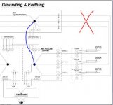
looking at post6 and just the left side:
You have a ground loop that runs through the hi pass channel and the low pass channel.
If any part of that loop shares a part of the route with any signal then interference will be added to the signal. That cannot be avoided.
You also have two more loops low pass to mid and hi pass to mid. This is three ground loops in the left side.
You also have 3 ground loop in the right side.
If any one of those six loops has a shared length in the route with a signal route you will get interference.
Now looking still at the left side.
You have three screened inputs.
The screen is the return for the signal coming into each amplifier.
The screen MUST be connected to the signal circuit at both ends to allow the signal circuit to work.
You have also connected all three screens to the Audio Ground at the input of the amplifier.
That is three more ground loops as soon as you connect any screens to a Source that commons the returns.
The same on the right side.
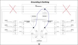
Does your amplifier produce extra noise when only one signal is connected?
Does the noise get worse when a second signal is connected?
You have to attenuate the interference in the loops. You MUST NOT break a two wire signal circuit.
A mono amplifier that separates the input Signal Ground from the PCB Power Ground+ Speaker Return, allows you to connect the signal circuit without creating a loop.
But it changes when you have more channels.
You then need to reference the input to the output.
You do this with a single wire that has a higher resistance to reduce the interference current in the loop that is created when the second channel is added.
looking at post6 and just the left side:
You have a ground loop that runs through the hi pass channel and the low pass channel.
If any part of that loop shares a part of the route with any signal then interference will be added to the signal. That cannot be avoided.
You also have two more loops low pass to mid and hi pass to mid. This is three ground loops in the left side.
You also have 3 ground loop in the right side.
If any one of those six loops has a shared length in the route with a signal route you will get interference.
Now looking still at the left side.
You have three screened inputs.
The screen is the return for the signal coming into each amplifier.
The screen MUST be connected to the signal circuit at both ends to allow the signal circuit to work.
You have also connected all three screens to the Audio Ground at the input of the amplifier.
That is three more ground loops as soon as you connect any screens to a Source that commons the returns.
The same on the right side.
Does your amplifier produce extra noise when only one signal is connected?
Does the noise get worse when a second signal is connected?
You have to attenuate the interference in the loops. You MUST NOT break a two wire signal circuit.
A mono amplifier that separates the input Signal Ground from the PCB Power Ground+ Speaker Return, allows you to connect the signal circuit without creating a loop.
But it changes when you have more channels.
You then need to reference the input to the output.
You do this with a single wire that has a higher resistance to reduce the interference current in the loop that is created when the second channel is added.
Last edited:
Hello Andrew...thanks and welcome to my nightmare!
By the way I have to add a precision here : the main Left and right inputs connectors are Neutrik six-pins connectors that don't have common ground/shields.
So pins 1, 3 & 5 are individuals Grounds and shields.
___________________________________________
Andrew,
You said:"looking at post6 and just the left side:
You have a ground loop that runs through the hi pass channel and the low pass channel."
I need precision here for better understanding: can you give the GndLoop point or describe it, please.
___________________________________________________________
To answer your questions :
1) Does your amplifier produce extra noise when only one signal is connected?...............No at all.
2) Does the noise get worse when a second signal is connected?.................Yes and it increases as you connect more inputs, together or to a source like let's say...a preamp.
___________________________________________________________
Here is a sequential description of added noise versus number of channel added.
1) One channel only, from side A...everything is fine.
2) You add a second channel from again side A...here you go with unacceptable noise level. Not hiss but 120Hz and harmonics.
3) You connect third and last channel from side A...around 4 to 6dB (?) of noise is added again.
4) Now you have all three channels of side A producing a certain amount of noise so now you simply connect one channel of side B: a real subtantial increment of added noise, larger than additions from 2) & 3).
5) You add a second channel of side B : again a good 4 to 6 dB of added noise.
6) Even connecting last channel of side B produces easily perceptibely audible noise increase.
You said:"You then need to reference the input to the output.
You do this with a single wire that has a higher resistance to reduce the interference current in the loop that is created when the second channel is added. ".
...You need to reference the input with the output. Yes this is quite fundamental but I did try something like this four days ago.
I just connected all shields in series with 16 ohms resistors on all individual Gnd inputs...the problem remainded.
___________________________________________________________
I'll try to get more into you post though as it looks interesting.
Note that it can take sometimes a full day to have a complete application of a solution but I'm still patient.
So please stay "connected".
Thanks.
Luke
Last edited:
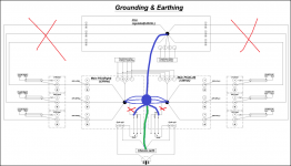
If you amplifier is quiet, with out anything plugged in, it's likely the loop problem is due to the ground currents flowing from the attached input sources.
If, and only if, your sources have a solid ground connection, one trick is to place a 15~22 ohm resistor in series with the screen connection inside your power amp as close to the PCB star as possible. What this does is force the ground loop currents to flow through the earth connections back to main earth and not through the screen.
I have incredibly quiet amp/ preamp set up, and I use this methodology.
Again, let me stress, all of the equipment must be solidly earthed.
I will try to post a drawing later today.
If you amplifier is quiet, with out anything plugged in, it's likely the loop problem is due to the ground currents flowing from the attached input sources.
If, and only if, your sources have a solid ground connection, one trick is to place a 15~22 ohm resistor in series with the screen connection inside your power amp as close to the PCB star as possible. What this does is force the ground loop currents to flow through the earth connections back to main earth and not through the screen.
I have incredibly quiet amp/ preamp set up, and I use this methodology.
Again, let me stress, all of the equipment must be solidly earthed.
I will try to post a drawing later today.
Hello Bonsai
You said:"If you amplifier is quiet, with out anything plugged in, it's likely the loop problem is due to the ground currents flowing from the attached input sources. "
Ground currents flowing through from the attached input sources...I never I had problem from a source that flows current to inputs but from a "Y splitter to 6" adapter that connect ALL inputs together. There is no current there, I guess.
Four of five days ago I applied your idea as in my Post#8 :"I just connected all shields in series with 16 ohms resistors on all individual Gnd inputs...the problem remainded."
Luke
Do a search for this 19 year old Neil Muncy (RIP) paper.
"Noise Susceptibility in Analogand Digital Signal ProcessingSystems"
NElL A. MUNCY,
Speedskater
Thanks. I have the paper but he speaks mainly about balanced systems which is not my case.
Gee...anyway...I should have made a balanced input system.
I would have had much more possibilities ...

Luke
This only means that or you drawing it is not correct/complete or you made a different connections not like in my drawing.
Anyway what is your power source diagram? And what are the connection of the power transformer?
Sesebe
My Gnd/Earth plan is correct and your suggestion has been perfectly implemented but I admit that the switch was not at the position you suggested, that means complete coupling from Earth to Gnd.
Instead it was at the "resistor parrallel to cap position" as shown on my drawing.
Luke
Last edited:
Read section 5.8 again. While Fig.7 Unbalanced Devices is rather primitive compared to the other drawings, but still you can puzzle a lot out from the balanced circuit figures.Speedskater
Thanks. I have the paper but he (Neil Muncy) speaks mainly about balanced systems which is not my case.
................................
Luke
One thing I would do differently is connect the Safety Ground/Protective Earth to the chassis near the power cord connector, using it's own mounting post.
While the Main Audio Ground should connect to the chassis near the I/O jacks.
- Status
- This old topic is closed. If you want to reopen this topic, contact a moderator using the "Report Post" button.
- Home
- Amplifiers
- Solid State
- Multichannel amplifier internal ground loop