I figured from the PSU pic that the R3,R4 are 150K and I can use 1W resistors. But can someone point me to the resistance values to be used for R6 & R7 which are near the rectifiers on the PSU board?
Thanks in advance.
Which PSU board are you using?
Which PSU board are you using?
It is the same that bandol designed smaller one same size as the amp boards. I got it printed and building it now and need to order the parts. Post # 2310
Thanks
Hi Boyet and manniraj,
There is no BOM for the power supply since the value of the components are dependent of the voltage you are using but I add a schema with the values that I am using
As an exemple for the Quasi with 42 V rail. I am using 4'700 uF 63 V electrolytic capacitor (50 V could be OK), what is important is the size of the capacitors :max 25 mm diameter ! R3 & R4 are bleeders to discharge the capacitors 100k will be OK, lower value will also be possible and will discharge faster but they will consume more in heat
R6 & R7 are high frequency filtering and R5 & R8 are current limiter for the optional LED...
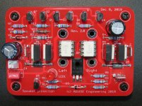
In the meantime I have received the PCB for the DC protection and mounted them, now I must test them and add them to the Quasi to finish it
Rgds,
Marc
There is no BOM for the power supply since the value of the components are dependent of the voltage you are using but I add a schema with the values that I am using
As an exemple for the Quasi with 42 V rail. I am using 4'700 uF 63 V electrolytic capacitor (50 V could be OK), what is important is the size of the capacitors :max 25 mm diameter ! R3 & R4 are bleeders to discharge the capacitors 100k will be OK, lower value will also be possible and will discharge faster but they will consume more in heat
R6 & R7 are high frequency filtering and R5 & R8 are current limiter for the optional LED...
In the meantime I have received the PCB for the DC protection and mounted them, now I must test them and add them to the Quasi to finish it
Rgds,
Marc
Attachments
PCB ready to buy?
Hy there,
Is there somewhere we can buy ready made PCBs?
Tnx.
Hi,
The schema and the BOM
Be careful some value indicated on the silkscreen aren't the same than those on the schema or the BOM which are the good one (at least for me). Most are not critical however except for the 1N4148 which replace the red LED.
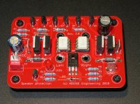
I have also added the PCB with components picture...
I hope I didn't forget anything.
Bon week-end,
Marc
Hy there,
Is there somewhere we can buy ready made PCBs?
Tnx.
hi,
first of all thanks to Ranchu32, AKSA, bandol83 and all contributors..
reading the thread for a while and want to build this amp but need some guidance..
i too ordered Marc's pcb design and boards came from pcb house,
thanks a lot Marc..
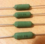
for R20-R21 (0R33) i found vishay AC03 wirewound 4w resistors in my parts bin, may i use it or it's better to order koa non-inductive ceramic resistors.
which one is preferable sonic wise?
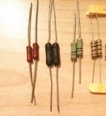
for R23 (10R) i have a few choices;
dale rs-2b wirewound, a metal-oxide one and two more but can't identify them (leftmost and rightmost)..
also maybe i can source allen bradley carbon comps from a local store but not sure will it be stable in there?
which one is better choice?
last but most important; i have dx psu pcbs from my symasm attempt a few years ago. may i use for this amp too?
thanks in advance..
first of all thanks to Ranchu32, AKSA, bandol83 and all contributors..
reading the thread for a while and want to build this amp but need some guidance..
i too ordered Marc's pcb design and boards came from pcb house,
thanks a lot Marc..
for R20-R21 (0R33) i found vishay AC03 wirewound 4w resistors in my parts bin, may i use it or it's better to order koa non-inductive ceramic resistors.
which one is preferable sonic wise?
for R23 (10R) i have a few choices;
dale rs-2b wirewound, a metal-oxide one and two more but can't identify them (leftmost and rightmost)..
also maybe i can source allen bradley carbon comps from a local store but not sure will it be stable in there?
which one is better choice?
last but most important; i have dx psu pcbs from my symasm attempt a few years ago. may i use for this amp too?
thanks in advance..
Attachments
Last edited:
Hi,
Finally I have finished the Quasi with the speaker protection installed and the good news is that the hum I had before disappear completely when I connected both speaker grounds to the common ground of the protection module
My design was a dual mono with separate power supply for each channel and the two GND were not connected ! That was the problem which give me the noise that I didn't have when I tested the amplifier board outside of the box because I had only one power supply !
For those who build this amplifier with my power supply PCB don't forget to connect both GND together
Now I only need to find a nice volume knob
Thanks to Ranchu32 and ASKA for this nice design and the good suggestions...
Best regards,
Marc
Attachments
Very well done, Marc, congratulations to a beautiful amp.
Could you compare it to other amps you have, to give a long term subjective view of this amp? You are a good critical listener, and your thoughts would be much appreciated.
This gives people a good yardstick by which to measure when they decide to build!
Hugh
Could you compare it to other amps you have, to give a long term subjective view of this amp? You are a good critical listener, and your thoughts would be much appreciated.
This gives people a good yardstick by which to measure when they decide to build!
Hugh
Hello Marc, I remain excellent congratulations, we could indicate the model and mark if possible of the transformer, has 4 secondary of 30vac? what power output? 8ohm speakers?Hi,
Finally I have finished the Quasi with the speaker protection installed and the good news is that the hum I had before disappear completely when I connected both speaker grounds to the common ground of the protection module
My design was a dual mono with separate power supply for each channel and the two GND were not connected ! That was the problem which give me the noise that I didn't have when I tested the amplifier board outside of the box because I had only one power supply !
For those who build this amplifier with my power supply PCB don't forget to connect both GND together
Now I only need to find a nice volume knob
Thanks to Ranchu32 and ASKA for this nice design and the good suggestions...
Best regards,
Marc
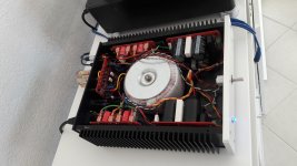
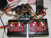
I have started my build after getting almost all the parts except the MJL3281AG BJTs which are on the way in a week or so. The PSU are completed with some hiccups with the R6/R7 resistors which I had to use atleast 2W ones not to smoke them. I used the same trafo as bandol 30v*4 secondaries and with the dual mono PSU getting 46.5vdc pretty stable as I used the 0.33R 5W resistors in the CRC. I hope this voltage is fine without any load and it may drop when connected to the amp boards.
I searched for the biasing/offset process based on the bandol's boards in the thread but could not find any specific ones. Can someone point to what should i be taking care during the biasing and if possible some steps would be very helpful. Here are the build pics and pretty small and cute cabinet and hopefully I should be able to fit everything into this
Thanks in advance.
I searched for the biasing/offset process based on the bandol's boards in the thread but could not find any specific ones. Can someone point to what should i be taking care during the biasing and if possible some steps would be very helpful. Here are the build pics and pretty small and cute cabinet and hopefully I should be able to fit everything into this
An externally hosted image should be here but it was not working when we last tested it.
An externally hosted image should be here but it was not working when we last tested it.
An externally hosted image should be here but it was not working when we last tested it.
Thanks in advance.
I know this is rather late in the game...
The 8dB NF is one deterrent. BC550/560 is 2dB. You can get lower still in single devices:
0.5dB 2SA1299 50V TO92,
1.5dB 2SA1190/C2855 (90V) 2SA1191/C2856 (120V), TO92
0.5nV/rt-Hz 2SA1083/84/85 /C2545/46/47 60/90/120V TO92
0.5dB 2SA979 100V SIP-5 dual diff-wired
0.5dB 2SA798 50V SIP-5 dual diff-wired
I stumbled across this part in a SOT-32-6 outline and thought it would be ideal for the LTP since it comprises two "super matched" 5401 NPN transistors in a single package. A quick search here revealed that AKSA have used this in some of their designs.
http://www.diodes.com/datasheets/ds30437.pdf
Are there any downsides apart from the reduced Pd, which won't be an issue for me in this application. Frankly I'm surprised this device isn't more widely used considering how important a close match is for the diff amp transistors.
The 8dB NF is one deterrent. BC550/560 is 2dB. You can get lower still in single devices:
0.5dB 2SA1299 50V TO92,
1.5dB 2SA1190/C2855 (90V) 2SA1191/C2856 (120V), TO92
0.5nV/rt-Hz 2SA1083/84/85 /C2545/46/47 60/90/120V TO92
0.5dB 2SA979 100V SIP-5 dual diff-wired
0.5dB 2SA798 50V SIP-5 dual diff-wired
Yes, Nauta. This was considered but high matching was important at low cost. In the final design a singleton KSA992 was used as I recall and the mechanical size issues precluded the SOT version for a single TO92. The original circuit is at #158 on page 16 of this thread.
The singleton ran about 650uA and the amp was never noisy, no one complained about noise, in fact I think it was very quiet.
In any event, this was designed and built a few years back now and unfortunately the chance is past, although extant VSQCs could easily be refitted with quieter transistors if necessary. Of course quieter transistors are not as important in line applications; only for very high gain phono preamps.
HD
Last edited:
Hi Manniraj,
Set 45mV across the 0.33R resistor on the CRC. This will set around 125mA quiescent on the output stage. Then set the offset to set less than positive or negative 15mV at the hot output wrt ground. Check after half an hour idling, and reset again to be sure.
Very nice work!
Cheers,
Hugh
Set 45mV across the 0.33R resistor on the CRC. This will set around 125mA quiescent on the output stage. Then set the offset to set less than positive or negative 15mV at the hot output wrt ground. Check after half an hour idling, and reset again to be sure.
Very nice work!
Cheers,
Hugh
Hi Manniraj,
Set 45mV across the 0.33R resistor on the CRC. This will set around 125mA quiescent on the output stage. Then set the offset to set less than positive or negative 15mV at the hot output wrt ground. Check after half an hour idling, and reset again to be sure.
Very nice work!
Cheers,
Hugh
Thanks Hugh, the 0.33R is the white cement resistor that I am using. I think I need to connect the DMM from underneath the board with some extending wires temporarily soldering. Which trimmer do I need to use for setting the 45mV of bias current and which trimmer to set the offset of around 15mV?
Hi Manniraj,
I cannot answer this because I'm not sure what pcb layout you are using!
However, on the pcb one trimmer will be marked 'BIAS' and the other will be OFFSET.
Even if you are not sure, put in the probes across the 0.33R resistor on the CRC and adjust one of them. If the voltage never changes, you are adjusting the offset. So move the probes to hot output for speaker and the ground, then set the OFFSET.
Then move to the other trimmer which you know must be the bias adjustment!
Hugh
Hi Manniraj,
I cannot answer this because I'm not sure what pcb layout you are using!
However, on the pcb one trimmer will be marked 'BIAS' and the other will be OFFSET.
Then move to the other trimmer which you know must be the bias adjustment!
Hugh
On my pcb designs I always mark "DC offset" and "bias" on the pcb.
Also I mark bias as "start ACW" (start anti clockwise) so they know which end is least bias current.
- Home
- Amplifiers
- Solid State
- Very simple quasi complimentary MOSFET amplifier