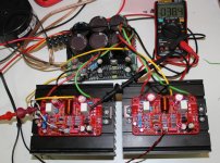
I add some pictures of the amplifier in test and how it will fit in a very slim enclosure .. and you will understand why I redesigned the PCB
Well done on getting your layout to work Marc! Looks great.
I'm still trying to work out how to squeeze my Phunk layout boards into the bigger brother of the case you have, so good job getting yours to fit in that small case!
I will throw this in!
In a quasi, the two output devices are used in dissimilar ways; one a source follower, and the bottom, a common emitter. This gives more second, third and fourth harmonic than a simple complementary output stage.
If you still stay with a quasi, using a nmos as a source follower and a npn as an emitter follower again means both devices are used in dissimilar ways, BUT we add this difference even more with different devices.
This even more accentuates the second, third and harmonic harmonics but distortion is no worse than two nmos, or npns in a same gender quasi.
By using a npn as the inverting output device we reduce the headroom losses on the negative half cycle. With a nmos as quasi, the headroom loss of the negative half cycle is around 7V. Using a npn, this loss is reduced to about 4V. This increase of 4V is matched by a higher headroom limit on the source follower because it is driven by a bootstrap which can throw beyond the positive rail; so this really improves clip by 8Vpp. If you start with 42V rails, a clip limit of 34Vp, which is 72W. It this is improved to 38Vp, the clip limit is increased to 90W (both in 8R) so this is a huge increase of power output of 25%, something you cannot ignore because power supplies cost money.
The harmonic profile is very good with a quasi, better than many complementary output stages.
HD
Another Quasi is singing...
Hi Hugh and others who helped me to build the Quasi, I am pleased to tell you that the second channel worked immediately, it is so easy when you don't put the wrong transistor
I have only listen them on small selves speakers but I can say that the quality is very good It is amazing for such a small amplifier, it is not exactly like a tube amplifier but for the price it is a winner ! I may try some time a combination of tube for voltage amplifier and transistors for the output stage to get rid of the heavy and expensive output transformer
In a previous post I asked what was the purpose of the bax circuit because I have found that I put a 22 pF instead of a 22 nF It was OK but I change it anyway... I also found that 500 ohms was OK for the bias trimmer because I didn't have 1k trimmer and I measured on the first channel about 270 ohms for 100 mA bias.
I will come back later when I will have listened the Quasi on better speaker and when I will have finished the assembly in the chassis...
Cheers
Marc
Hi Hugh and others who helped me to build the Quasi, I am pleased to tell you that the second channel worked immediately, it is so easy when you don't put the wrong transistor
I have only listen them on small selves speakers but I can say that the quality is very good
It is amazing for such a small amplifier, it is not exactly like a tube amplifier but for the price it is a winner ! I may try some time a combination of tube for voltage amplifier and transistors for the output stage to get rid of the heavy and expensive output transformer In a previous post I asked what was the purpose of the bax circuit because I have found that I put a 22 pF instead of a 22 nF
It was OK but I change it anyway... I also found that 500 ohms was OK for the bias trimmer because I didn't have 1k trimmer and I measured on the first channel about 270 ohms for 100 mA bias.I will come back later when I will have listened the Quasi on better speaker and when I will have finished the assembly in the chassis...
Cheers
Marc
Attachments
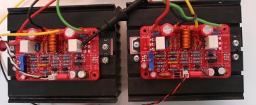
That PCB is superb
That PCB is very good. The output devices are well away from any electrolytic caps and if they get hot the PCB won't be baked so much.
It would be very interesting to compare the sound to the Mooley.
Regards ....
I will come back later when I will have listened the Quasi on better speaker and when I will have finished the assembly in the chassis...
That PCB is very good. The output devices are well away from any electrolytic caps and if they get hot the PCB won't be baked so much.
It would be very interesting to compare the sound to the Mooley.
Regards ....
Thanks for your nice comments, I also like these PCB because power transistors are easy to mount as they are not under the PCB and I think the heat dissipation is better As a bonus the PCB can be smaller and this form factor is very convenient for slim enclosure...
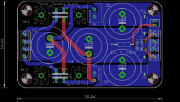
I like the format so much that I have made a very compact power supply C-R-C board for the quasi with the same dimension and they can be fixed on the heatsink too.
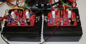
While I am doing that I am listening the Quasi on better speakers (Yamaha bookshelves speaker) and even if I didn't test them yet on my "Alon" or "Focal" the result is very impressive, particularly in the bass you can feel the air moving fron these small speakers, with bigger ones it will be terrific
I am still with 40 VDC power supply using a small 2 x 25 VAC 120 VA toroidal transformer that I have used for a MyRef gain-clone designed by Mauro Penasa, I know it is a little bit too small but it is not very warm, I may try later with a new 300 VA transformer, that I have just received, with 2 x 35 VAC output that should give me about 47 VDC...
Now I have to work on the DC protection for the speakers
Cheers,
Marc
As a bonus the PCB can be smaller and this form factor is very convenient for slim enclosure...I like the format so much that I have made a very compact power supply C-R-C board for the quasi with the same dimension and they can be fixed on the heatsink too.
While I am doing that I am listening the Quasi on better speakers (Yamaha bookshelves speaker) and even if I didn't test them yet on my "Alon" or "Focal" the result is very impressive, particularly in the bass you can feel the air moving fron these small speakers, with bigger ones it will be terrific
I am still with 40 VDC power supply using a small 2 x 25 VAC 120 VA toroidal transformer that I have used for a MyRef gain-clone designed by Mauro Penasa, I know it is a little bit too small but it is not very warm, I may try later with a new 300 VA transformer, that I have just received, with 2 x 35 VAC output that should give me about 47 VDC...
Now I have to work on the DC protection for the speakers
Cheers,
Marc
Attachments
Hello,
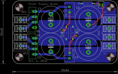
New version for the CRC power supply because of connectors availability
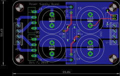
I have made two different rectifier schemes, don't know which one is the best ? Only one bridge with good diodes or two bridges with standard rectifiers ?
I am not in hurry since I will go to Phoenix AZ in 10 days and I will not get the PCB before my trip
Best regards,
Marc
PS: Still listening the Quasi on Yamaha bookshelves speakers, I have tested SACD titles and it is really impressive, will try soon on better speaker
New version for the CRC power supply because of connectors availability
I have made two different rectifier schemes, don't know which one is the best ? Only one bridge with good diodes or two bridges with standard rectifiers ?
I am not in hurry since I will go to Phoenix AZ in 10 days and I will not get the PCB before my trip
Best regards,
Marc
PS: Still listening the Quasi on Yamaha bookshelves speakers, I have tested SACD
titles and it is really impressive, will try soon on better speaker Attachments
Hello Marc,
nicely done. just one suggestion. make the diode output go to smoothening caps and then connect the cap to the resistor. i.e. DC supply must be taken from cap terminals.
4th paragraph from last.
Project 101 - High Power, High Fidelity Lateral MOSFET power amplifier
Also you could consider adding transformer snubbers.
RingNot: power supply for chip amps. Bare PCBs and/or assembled+tested units
Go for 1st option of design, dual bridges alway lower noise.
Last edited:
Hello Prasi, JPS and XRK,
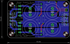
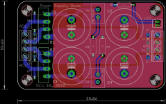
Thanks for your feedback, I have added the snubber on the dual rectifier version which seem to be better. I have not understood the other comments regarding copper balancing, may be my english is not good enough ? And I don't understand why there should be a resistor to the between the two capacitors GND ?
Here is the modified layout with the snubber...
Rgds,
Marc
Attachments
Bonjour Cognac,
Do you know how to do it with Eagle when a track is already made on one side ?
Thanks,
Marc
Use line command (symbol: a slanted line) and start placing a line (of appropriate width) from the center of first pad to center of next pad. The active layer should be opposite to the one already placed.
regards
Prasi
- Home
- Amplifiers
- Solid State
- Very simple quasi complimentary MOSFET amplifier