VSQHA
Hello Hugh and Fellas.
I only have saved files to be sure for service my own failures, if possible.
If Thimios and Other don't helping with shared results of work, me (other?) staying lost in forest.
No reason to thank, Hugh- Thanks back for your help and attention.
As Ranchus thread started here i was following up to page 75 and save notices
in a Word DOC(X)-PDF.
I show it here, so any interested could use it for own need now.
Yes, thanks Colin, that is the reference, #2246 on page 245. But note that schem indicates 32V rails, yours may be higher.
What you really need are the bias points for the output stage, and the reference voltage for the input transistor base, shown here at -1.95V.
My thanks to Bangla H!
Hello Hugh and Fellas.
I only have saved files to be sure for service my own failures, if possible.
If Thimios and Other don't helping with shared results of work, me (other?) staying lost in forest.
No reason to thank, Hugh- Thanks back for your help and attention.
As Ranchus thread started here i was following up to page 75 and save notices
in a Word DOC(X)-PDF.
I show it here, so any interested could use it for own need now.
Attachments
All my test is here in the thread post#346
I haven't test this pcb so i can't know if any bag.
Please use primary side protection, variac or lamp.
Use protective resistors in fuse position.
If you can't read resistor code use ohmmeter to be sure.
When chouse alternative parts be sure that is pin compatible or use the net for proper installation.
Again... schematic is bug free now but pcb is unknown to me.
Regards
Thimios.
Last edited:
doodling
yes Hugh ,but was most helpful here and there to come on right way.
As a ZERO- Expert i was puzzeling, a bit for me, some comments.
Very simple quasi complimentary MOSFET amplifier
Sorry Thimios, if it was not right to name you here.
Bandols Bord is a mix of Prasi and DACZ in unique size.
Your actually comments are right.
All work must be done in proper way.
I know you are more busy in Valery's & Jeff's Projects now.
Regards
yes Hugh ,but was most helpful here and there to come on right way.As a ZERO- Expert
i was puzzeling, a bit for me, some comments.Very simple quasi complimentary MOSFET amplifier
Sorry Thimios, if it was not right to name you here.
Bandols Bord is a mix of Prasi and DACZ in unique size.
Your actually comments are right.
All work must be done in proper way.
I know you are more busy in Valery's & Jeff's Projects now.
Regards
Hi,
I am building the second channel with the KSC1845 (instead of the 2N5551) that I should receive tomorrow from Mouser, and I have several question to be sure to avoid other mistake
1) On two schemes from DACZ REV 2 from AUG 22, it is indicated KSA1845 on one and KSC1845 on another, I think the KSC1845 the good one because the KSA1845 does not exist
2) For R19, I have only resistor in 0309 package or 120 ohm, can I use a 100 ohm like indicated another schema and as used by XRK because I have made the layout for 0207 resistor size ! I put a 100 ohm in the first channel in fact but since I had power level problem I am more careful now
3) I will use a 5.1 ohm resistor for R17 as it was confirmed that it should be OK and XRK used 10 ohm witout problem !
3) I will use FQA40N25 MOSFET and MJL3281AG bipolar to accept a dual 35 V 300 VA power supply transformer which may give up to 47 VDC after rectifier bridge, is it acceptable for this amplifier or should I use a 30 V version ?
Thanks for your help, I hope this second channel will play music soon and that I can repair the first one after...
Regards,
Marc
Nothing wrong dear!
As a ZERO- Expert
Very simple quasi complimentary MOSFET amplifier
Sorry Thimios, if it was not right to name you here.
Bandols Bord is a mix of Prasi and DACZ in unique size.
Your actually comments are right.
All work must be done in proper way.
I know you are more busy in Valery's & Jeff's Projects now.
Regards
Hi Hugh,
I have read in your post 1795 this : "There is switching taking here; the diode, the resistor, and quasi. This switching causes higher harmonics. When you measure the 120/150 combo, you get this at +20dB output, attached as Ranchu120-150.
When you measure the 150/150 combo, it's very similar here attached. I can actually see no reason to make these resistors, R19 and R14, different. They should be the same value; in this situation, I'd use 120R for both. In the FFTs, all quiescents were set to 125mA for correct comparison.
You suggest to use 120R for both R14 and R19, but can I use 150R or 100R with similar result (I still haven't 120R in 0207 package ) ?
Since I am waiting the KSC1845 from Mouser I read all the thread and I have found very interesting information
Best regards,
Marc
Second try is the good one !
Hi Hugh, Bangla, Vrystaat,
Thanks for your help, the second channel is working loud
I think the mistake on the first channel with the 2N5551 mounted instead of the KSC1845 destroyed the KSA1381 and that was the reason why I could not play it loud
Now it worked flawlessly immediately when connected, I was able to adjust the DC offset and the bias without problem and it is not very warm with a power supply of +/- 41 VDC and a bias of 100 mA
What I have changed :
1) the 2N5551 replaced by the KSC1845 of course, my biggest error
2) the two red LED replaced by two 1N4148
3) the 1.5k R9 by a 1.8k
4) the 150R R14 and the 120R R19 replaced by two 100R as suggested by Hugh
5) the IRFP240 by the FQA40N25 (a big package !)
6) the 2SC5200 by the MJL3281AG
7) the 500R VR2 by a 1k
8) the 22uF C3 by a 47 uF
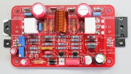
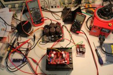
As several said already the quality of the sound is very good, for the time being I am only listening in my lab with only one small speaker, but it is very promising, not completely like a tube amplifier but with some nice similarities
I add some pictures of the amplifier in test and how it will fit in a very slim enclosure Aliexpress.com: Acheter Boitier en aluminium 2107 k Complet En Aluminium Amplificateur cas/Mini AMP Cas/Preampli Boite/PSU Boitier 212 * 70*257mm de psu enclosure fiable fournisseurs sur HIFI amplifier spare parts center Store and you will understand why I redesigned the PCB
Best regards,
Marc
Hi Hugh, Bangla, Vrystaat,
Thanks for your help, the second channel is working loud
I think the mistake on the first channel with the 2N5551 mounted instead of the KSC1845 destroyed the KSA1381 and that was the reason why I could not play it loud
Now it worked flawlessly immediately when connected, I was able to adjust the DC offset and the bias without problem and it is not very warm with a power supply of +/- 41 VDC and a bias of 100 mA
What I have changed :
1) the 2N5551 replaced by the KSC1845 of course, my biggest error
2) the two red LED replaced by two 1N4148
3) the 1.5k R9 by a 1.8k
4) the 150R R14 and the 120R R19 replaced by two 100R as suggested by Hugh
5) the IRFP240 by the FQA40N25 (a big package !)
6) the 2SC5200 by the MJL3281AG
7) the 500R VR2 by a 1k
8) the 22uF C3 by a 47 uF
As several said already the quality of the sound is very good, for the time being I am only listening in my lab with only one small speaker, but it is very promising, not completely like a tube amplifier but with some nice similarities
I add some pictures of the amplifier in test and how it will fit in a very slim enclosure Aliexpress.com: Acheter Boitier en aluminium 2107 k Complet En Aluminium Amplificateur cas/Mini AMP Cas/Preampli Boite/PSU Boitier 212 * 70*257mm de psu enclosure fiable fournisseurs sur HIFI amplifier spare parts center Store and you will understand why I redesigned the PCB
Best regards,
Marc
Attachments
Marc,
Good to know that you have the second channel running smoothly now, and hope you get stereo sound soon. Do inform us of your listening listening impressions again when you have more hours of playback with stereo and good speakers.
Also if I may ask, did you mange to test your speaker protection PCBs?
Good to know that you have the second channel running smoothly now, and hope you get stereo sound soon.
Do inform us of your listening listening impressions again when you have more hours of playback with stereo and good speakers.Also if I may ask, did you mange to test your speaker protection PCBs?
Last edited:


Bonjour,
Thanks for your nice words
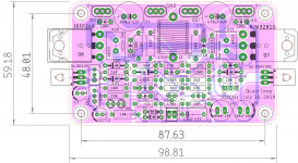
As promised, since the "low profile Quasi PCB" is now singing, I put the Gerber files for those who could be interested by this slim PCB. There were already 4 or 5 versions of the very successful amplifier made by Ranchu, Hugh and many others who tested it and liked it, so I am the "Number 6" like in "The Prisoner" The Prisoner - Wikipedia
I also give my thanks to Prasi who kindly send me his schematic file to save some time and checked my PCB, and thanks to Philippe who made the nice coil of the Quasi 2
I will add a corrected schema and BOM with the last components value in an other post but you can already found the Gerber files here...
By the way, when I wrote the part list, I found that I make an other mistake with C9, I put a 22 pF instead of a 22 nF It was working fine even with this error, please can I ask what is the purpose of this Bax capacitor ?
Au revoir,
Marc
Thanks for your nice words
As promised, since the "low profile Quasi PCB" is now singing, I put the Gerber files for those who could be interested by this slim PCB. There were already 4 or 5 versions of the very successful amplifier made by Ranchu, Hugh and many others who tested it and liked it, so I am the "Number 6" like in "The Prisoner" The Prisoner - Wikipedia
I also give my thanks to Prasi who kindly send me his schematic file to save some time and checked my PCB, and thanks to Philippe who made the nice coil of the Quasi 2
I will add a corrected schema and BOM with the last components value in an other post but you can already found the Gerber files here...
By the way, when I wrote the part list, I found that I make an other mistake with C9, I put a 22 pF instead of a 22 nF
It was working fine even with this error, please can I ask what is the purpose of this Bax capacitor ?Au revoir,
Marc
Attachments
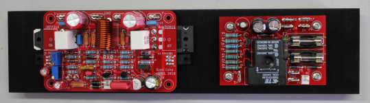
Hi,
The schema and the BOM
Be careful some value indicated on the silkscreen aren't the same than those on the schema or the BOM which are the good one (at least for me). Most are not critical however except for the 1N4148 which replace the red LED.
I have also added the PCB with components picture...
I hope I didn't forget anything.
Bon week-end,
Marc
Attachments
Hello Prasi,
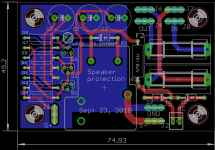
I have tested the protection module, and guess what ? I have again a transistor with the wrong pinout


This make me crazy, it is not a Japanese transistor name, it it the BC639, but it has the Japanese pinout ECB https://www.onsemi.com/pub/Collateral/BC635-D.PDF instead of the European one for BCxxx EBC That never happen to me with tubes
After I cross the legs again it worked, but I think I have to change one resistor value because the relay open only if 7 VDC is present, I think it is too much ?
The power on delay is OK, about 2 seconds Attached is the modified PCB...
Best regards,
Marc
I have tested the protection module, and guess what ? I have again a transistor with the wrong pinout
This make me crazy, it is not a Japanese transistor name, it it the BC639, but it has the Japanese pinout ECB https://www.onsemi.com/pub/Collateral/BC635-D.PDF instead of the European one for BCxxx EBC
That never happen to me with tubes After I cross the legs again it worked, but I think I have to change one resistor value because the relay open only if 7 VDC is present, I think it is too much ?
The power on delay is OK, about 2 seconds
Attached is the modified PCB...Best regards,
Marc
Attachments
- Home
- Amplifiers
- Solid State
- Very simple quasi complimentary MOSFET amplifier