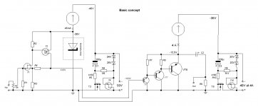
A concept of the present single-ended amplifier is based on decoupling of all signal parts of the schematics from the power supply rails. This concept has come as a result of extensive empirical trial-and-listening efforts. The decoupling is achieved due to surrounding of the active parts of the schematics by Current Sources and Source Followers. The preliminary voltage amplification stage provides also necessary bias to the base of T6, thus avoiding coupling capacitor. This stage uses a kind of NFB which is usually called “current-type NFB”, in fact the NFB voltage is not determined by output current, this notion simply means that NFB voltage is applied to a low-impedance point at the schematics, and relatively high current is needed through NFB divider (current via R4-R3 is much higher that via T1). Voltage amplification is approximately equal to R4/R3, and voltage at the output is adjusted by R2. The simplicity of schematics has also drawbacks, selection of T1 is needed, as well as definite adjustments.
Maximum linearity is not the main goal at this design, but, taking into account that the NoGNFB output stage works at most linear high-current region, THD is expected well below 0,1% (not measured by me, honestly speaking I find no sense in THD measurements). The passband is well above 1MHz, square-wave response of the preliminary stage is perfect (will be shown), but, after output stage, I decided to allow few oscillations at the fronts (VHF bjt power transistors similar to MRF422 are used at the output), since output stage is not in the GNFB loop.
This approach does not pretend to state, that traditional non-rail-decoupled solutions could not produce good sound, but they need much more expensive and sophisticated developments, that is not usually acceptable for DIYers. With the rails-decoupled approach one benefits in the following:
1) no need in high-quality and expensive power supply components;
2) no need in expensive power line cables and in the “quantum purifiers” of the line voltage;
3) the design is less exposed to the issues of electro-magnetic coupling between high and low current parts of schematics;
4) fears that the output capacitor compromises a sound have no grounds, at any schematics capacitors are inevitable parts of the output signal chains; output cap also serves as speaker protection.
Attachments
Last edited:
Hi Vladimir,
Please get me right, I am not trying to criticize - just trying to understand.
Circuits based on T3, T4 and T9, T10 are voltage regulators.
So is it "decoupled" by the regulators?
"Current-type NFB" or CFB term does not mean NFB voltage is determined by the output current. It means that the circuit controlled by NFB is controlled by current, not voltage.
I put it in a bit different way.
If a high-resistance NFB is applied to the low resistance input of the circuit, controlled by this NFB, then it is current, controlling the circuit. So this FB is CFB.
Otherwise, if the low-resistance NFB is applied to the high-resistance input of the controlled circuit, then it is a voltage, controlling the circuit, and this is VFB.
In your case it is CFB af the feedback is applied to the low-resistance point (source of T1) with a relatively high resistance of R4.
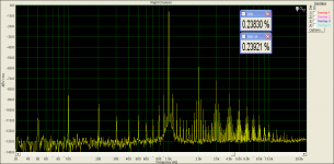
I disagree with the statement that THD is no sense to measure. It is definitely an indicative parameter, but giving a good indication. As soon as you see some high THD (like 0.5%), it is important to look at the spectrum of those harmonics. If, for example it mostly consists of the 2-nd one, then the sound most likely be ok ("warmer", "richer" than source, but ok). If the odd ones are strong (like 3, 5) - then it will sound awful. Well, nothing new - just trying to explain my point of view. I personally prefer the "transparent" amps, the ones that "don't sound". Those are definitely highly linear, low-THD ones.
There's nothing wrong with the output capacitor, as far as it is a good one, new capacitor. The problem is that they degrade over the time. Well, everything in the world degrades over the time, but electrolytic capacitors degrade faster") That's ok, but requires additional attention.
That's ok, but requires additional attention.
Anyway, I will be very interested in seeing some measures, wave-forms, listening impressions from the live prototype.
BR,
Valery
Please get me right, I am not trying to criticize - just trying to understand.
Circuits based on T3, T4 and T9, T10 are voltage regulators.
So is it "decoupled" by the regulators?
"Current-type NFB" or CFB term does not mean NFB voltage is determined by the output current. It means that the circuit controlled by NFB is controlled by current, not voltage.
I put it in a bit different way.
If a high-resistance NFB is applied to the low resistance input of the circuit, controlled by this NFB, then it is current, controlling the circuit. So this FB is CFB.
Otherwise, if the low-resistance NFB is applied to the high-resistance input of the controlled circuit, then it is a voltage, controlling the circuit, and this is VFB.
In your case it is CFB af the feedback is applied to the low-resistance point (source of T1) with a relatively high resistance of R4.
I disagree with the statement that THD is no sense to measure. It is definitely an indicative parameter, but giving a good indication. As soon as you see some high THD (like 0.5%), it is important to look at the spectrum of those harmonics. If, for example it mostly consists of the 2-nd one, then the sound most likely be ok ("warmer", "richer" than source, but ok). If the odd ones are strong (like 3, 5) - then it will sound awful. Well, nothing new - just trying to explain my point of view. I personally prefer the "transparent" amps, the ones that "don't sound". Those are definitely highly linear, low-THD ones.
There's nothing wrong with the output capacitor, as far as it is a good one, new capacitor. The problem is that they degrade over the time. Well, everything in the world degrades over the time, but electrolytic capacitors degrade faster
That's ok, but requires additional attention.Anyway, I will be very interested in seeing some measures, wave-forms, listening impressions from the live prototype.
BR,
Valery
Please get me right, I am not trying to criticize - just trying to understand.
Circuits based on T3, T4 and T9, T10 are voltage regulators.
So is it "decoupled" by the regulators?
In your case it is CFB af the feedback is applied to the low-resistance point (source of T1) with a relatively high resistance of R4.
Anyway, I will be very interested in seeing some measures, wave-forms, listening impressions from the live prototype.
Hello, Valery
Yes, as "rails decoupling" I imply here simply prevention of any signal currents passing through power supplies circuitry. So, correspondingly connected voltage regulators and current sources just execute this function.
Thanks for clarifying with the CFB term, this is just the proper term here.
I also ask to admit one point, the THD and spectrum issues do not play in my diy acoustic research, and not because of stupid stubbornness, simply all recent designs (more than 10) all have "proper" spectra and sound pure, without any harshness or darkness, usually better than many good tube and SS amps (I used to listen in my system amps like Restek, Yamaha A-3000, A-2000, Yamaha B2, MBL, Accuphase, tube NEM A300SE, tube SE based on GM70, tube PP, many others).
I've found, that with high-level system (the my is quite high level), factors other than THD and spectra are much more important, and sound can change quite dramatically without any essential changes in spectra (for instance, bad cap is used, or low-quality volume pot).I do not admit using of ALPS RK27 pots, they kill the sound dramatically. So, I would be very grateful to all participants not to accent THD issues in this thread.
This is just the point of this thread, simply pay attention to the "rails decoupling", compare sounds of with and without decoupling devices, with identical active part of schematics (at that, THD will measure similarly). I understand, that the "rails decoupling" is hardly applicable to class AB designs, so my findings are pertinent to specific and narrow band of amp designs.
Last edited:
Thanks for sharing Vladimir, I look forward to understanding more about this original approach.
Do you know what kind of impedance you achieved with your o/p CCS in the real world amp ?
Yes, I did measure it, both directly by immittance meter, and indirectly by observing the output voltage drop after connecting 5,1 Ohms resistive load.
Both measurements are close to 0,1 Ohms.
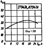
In this respect I would mention, that very low Rout values give no warranty for correct bass sound (I judge with high quality recordings of double-bass, bass-guitar and big drums). Subjective bass depends on many aspects of definite amp - definite speaker interactions, one needs a kind of empirical adjustment. Some of my SE amps, which include output stage in the NFB loop, with Rout close to 0,01 Ohms, produce "less correct" bass. I've found, that a kind of non-linearity, given by VHF power bjt used (their "h21 vs collector current" curve is not flat, it does not drop at 3...5A, on contrary, it continues growing up to 25A), allows to improve amp-speaker interaction, most probably by better counter-action to speaker back-emf. Some people arrange some positive feed-back, adjusted to their speakers. In my case, with PMC EB1i speakers, just the "non-linearity" caused by rising h21 is just OK. One should also bear in mind, that GNFB is usually not a good cure for improving bass, it does change bass, but not necessarily in correct manner.
Important also that the passband would have low-end frequency less than 1 Hz at 4 (better 2) Ohms, this prevents phase shifts. I notice quite well improving of bass with increasing output cap (100000uF is better than 50000uF). Output caps as 4700uF or 10000uF at numerous schematics make me lough.
Last edited:
Thx ur quick reply, but actually I was interested in how high the CCS impedance was rather than how low the o/p impedance was
edit - actually interesting to know both because dividing CCS impedance by OP impedance will give an idea of how much PSU noise is suppressed - always high on my list of priorities
edit - actually interesting to know both because dividing CCS impedance by OP impedance will give an idea of how much PSU noise is suppressed - always high on my list of priorities
Last edited:
Thx ur quick reply, but actually I was interested in how high the CCS impedance was rather than how low the o/p impedance was
edit - actually interesting to know both because dividing CCS impedance by OP impedance will give an idea of how much PSU noise is suppressed - always high on my list of priorities
In my case CCS impedance is near 100 Ohms. It depends on actual CCS solution, but in my case I used 15pcs of power jFETs in parallel, with common gate-source resistors. Every jFET gives around 1200 Ohms of dU/dI at the saturation region. Moreover, G-S resistors create additional local NFB. So, around 0,1% of output signal current "penetrates" to the PS rail.
Concerning this your question I would like to add, that not so important how deep the rail noise suppression is in general, more important how fast the suppression is, whether the rail noise suppression involves long NFB chain with "ringing" or not. In other words, transient behaviour is mor important than after equilibration.
Last edited:
Concerning this your question I would like to add, that not so important how deep the rail noise suppression is in general, more important how fast the suppression is, whether the rail noise suppression involves long NFB chain with "ringing" or not. In other words, transient behaviour is more important than after equilibration.
Agreed 100%
For me any kind of ringing, particularly ultrasonic, is sonic public enemy No:1 and having a high FB assisted PSRR that introduces transient ringing is pointless.
Last three years I been working on a GFB design and eliminating noise & ringing from every stage was a high priority.
In other words, transient behaviour is mor important than after equilibration.
100% correct!
If you've not already looked at it, many of these concepts have already been dealt with in various (mostly non-fashionable) valve amps - consider concept of "Ultrapath" capacitors (and all the impacts of them)
Sometimes a balanced circuit is just easier...
Sometimes a balanced circuit is just easier...
If you've not already looked at it, many of these concepts have already been dealt with in various (mostly non-fashionable) valve amps - consider concept of "Ultrapath" capacitors (and all the impacts of them)
Sometimes a balanced circuit is just easier...
Even without referring to "ultrapath", tube schematics typically reveal PS rail decoupling from the output signal, by using Choke Input PS. The choke acts a bit similar to current source.
Actually a choke would probably work very well in the o/p in ur design Vladimir - did you ever try one. I think 5 - 10mH + 0.1R might be about right
Chokes work far more efficiently & effectively in low voltage / high current environments than they do in high voltage / low current environments.
Strange that they feature so much in tube designs and so little in solid state designs.
Chokes work far more efficiently & effectively in low voltage / high current environments than they do in high voltage / low current environments.
Strange that they feature so much in tube designs and so little in solid state designs.
Actually a choke would probably work very well in the o/p in ur design Vladimir - did you ever try one. I think 5 - 10mH + 0.1R might be about right
Chokes work far more efficiently & effectively in low voltage / high current environments than they do in high voltage / low current environments.
Strange that they feature so much in tube designs and so little in solid state designs.
Proper chokes for ampear currents are monsters, one design was discussed at Pass forum. Soundwise - their benefits have not been prooved yet. For comparison - I have an industrial 300B SE tube amp, with choke input PS, with interstage trafos, with big output trafos. Although its sound is very very nice and better (in transparency and easy to listen) than 99% of industrial SS, I can not say that it is better than my DIY in any one aspect. So I doubt in superiority of chokes over proper CCS, except for efficiency.
All these simple SE class A amplifiers that I have tried have very, very poor PSRR (power supply rejection ratio). Any supply ripple is usually reflected at the output with poor attenuation, like 40dB or less. So these amps do need clean power supplies and thus probably an effort to make a constant current load for the power supply. Even then there is a basic ripple, which may be quite high according to amplifier idle current. So the question is if it is not better to improve the amplifying circuitry than to try to make an overrated power supply (filters, big capacitors). And, powers supply residuals may be very easily measured, so we may easily have answers if the effort was worth to spend.
Attachments
Member
Joined 2009
Paid Member
Fascinating design approach and I'm very interesting in the choice of output power transistor, I believe your thoughts here are very good, the attention to detail for the transistor parasitics is changing my thinking about SS amplifiers.
Amplifier or PSU ? - I see them as one and the same and see little profit in dealing with them separately for SE amplifiers.
Amplifier or PSU ? - I see them as one and the same and see little profit in dealing with them separately for SE amplifiers.
All these simple SE class A amplifiers that I have tried have very, very poor PSRR (power supply rejection ratio). Any supply ripple is usually reflected at the output with poor attenuation, like 40dB or less. So these amps do need clean power supplies and thus probably an effort to make a constant current load for the power supply. Even then there is a basic ripple, which may be quite high according to amplifier idle current. So the question is if it is not better to improve the amplifying circuitry than to try to make an overrated power supply (filters, big capacitors). And, powers supply residuals may be very easily measured, so we may easily have answers if the effort was worth to spend.
I know very well the Macura@Bunta SE power follower, this speaks about your experience with class A. Nevertheless, I believe, that any class mark at which amps could operate, predetermines sound quality only very partially. IMO, traditional SE class A solutions (e.g. JLH or Macura@Bunta) can differ from typical class AB only in respect of crossover distortions and of their effects at NFB loop. But, some non-traditional solutions can bring something new to sound quality. IMO, solution like in this thread gives evident benefits to sound quality, but will never come to industry, due to efficiency, output power and hardware design limitations.
Fascinating design approach and I'm very interesting in the choice of output power transistor, I believe your thoughts here are very good, the attention to detail for the transistor parasitics is changing my thinking about SS amplifiers.
Amplifier or PSU ? - I see them as one and the same and see little profit in dealing with them separately for SE amplifiers.
I used the russian KT947A, its base current transfer ratio is like this. I have found that more or less close substitute for them are MRF422.
Attachments
Member
Joined 2009
Paid Member
I used the russian KT947A, its base current transfer ratio is like this. I have found that more or less close substitute for them are MRF422.
My gosh, have you seen the price of the MRF422 on eBay these days
I'm afraid this will be a show-stopper for many, but there is much of importance to learn from you on this design approach.
Nice disign Vladimir, what`s the feedback factor? Is it high the open loop bandwidth design?
What transistors you used for a output triple and have you experienced oscillations? What about stability with 100nF on the amp output?
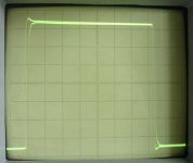
This is a square-wave responce of the preliminary stage, voltage amplification Vout/Vin = 22,8 , 100kHz, 20V p-p.
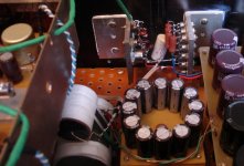
The next picture is how the output stage is assembled. transistors of the output stage are BC107B, KT904A, KT947A.
Possible substitutes KT904A -- 2SC3748; KT947A -- MRF422.
Attachments
Last edited:
- Status
- This old topic is closed. If you want to reopen this topic, contact a moderator using the "Report Post" button.
- Home
- Amplifiers
- Solid State
- Rails Decoupled SE Amplifier