But how do I get more current through the drivers?
current thru the drivers will be dictated by the requirements of the load...
Newb question. How do you screen the input tranies for good matched vbe at operating currents? Got a link to a circuit for that?
Thanks, Terry
Leach has a method for that, if you read his papers you will find it in the 1980 Audio article about the double barreled amp...
other links...
http://www.diyaudio.com/forums/solid-state/93898-matching-transistors-measuring-hfe.html
nice project here...
http://www.musicfromouterspace.com/analogsynth_new/TRANSISTORMATCHER/TRANSISTORMATCHER.html
Nelson Pass....
https://www.passdiy.com/project/articles/matching-devices
Rod Elliot....
Matching Power and Driver Transistors
Not when the amplifier is being checked during quiescent operation.
yes of course.....

seriously, if you want more current thru the drivers, decrease R35 from 100 ohms to say 56 ohms....
Member
Joined 2009
Paid Member
the drivers are 50W devices.
Maximum fT occurs when Ic~600mA to 1100mA
Flattish (linear) hFE from 150mA to 800mA
If the quiescent driver currents only approach these values at very high outputs then the CHANGE in parameters will seriously affect stability margins as the devices move from 12mA to 1000mA during loading with a speaker.
Setting up the drivers with "only" 12mA seems wrong.
The 0mV and 1mV stopper measurements suggest the drivers are currently even lower than 12mA.
56R? - I've never seen the blameless with so much current through the drivers. I think Roender used a lot of current in his design, but it had CFP drivers.
a question was asked by Ranchu wanting to get more current out of the drivers...and i took it to mean at quiescent state, that is why....
otoh, to get less current in the drivers, increase the value from 100 ohms to 220 ohms..
Last night before I went to bed I measured the Vdrop across the driver base stoppers. I'm still using a low voltage supply / 35VDC rails for testing.
NPN = ~2.2mV
PNP = ~1mV
Concerned about the huge imbalance between these complimentary pairs, I grabbed some MJE15030/31 samples from my parts bin and measured the gain. The NPN devices have a fairly tight gain distribution as do the PNP parts. But the difference between PNP and NPN parts is huge - I can hardly believe these are marketed as complimentary pairs! I think it would be virtually impossible to find a MJE15030 and MJE15031 that match within 10%
Thinking that I may have bad batch of MJE15030 or MJE15031 devices I did the same testing with some MJE15032 and MJE15033 and found the same with these.
Driver emitter resistor:
I've studied several Linn/Blameless circuits and this resistor is usually in the range 100R to 220R, with 150R and 180R as common values. I can't recall any with <100R in this position.
So I'm not against the idea of reducing this value on my circuit but curious why others haven't done this?
pnp's are holes, npn's electrons so that they will never be the same...
unless you get hundreds and screen for equal readings,
but that is not needed and will cost you more...
because the "others" did not find it absolutely necessary....
unless you get hundreds and screen for equal readings,
but that is not needed and will cost you more...
So I'm not against the idea of reducing this value on my circuit but curious why others haven't done this?
because the "others" did not find it absolutely necessary....
Member
Joined 2009
Paid Member
There's enough GNF to take care of the slight imbalances between NPN and PNP devices, I don't see too much to worry about but it would be interesting to know how much difference close matching of the drivers would make to the sound. It is common wisdom and scientifically beneficial to match the LTP devices as closely as possible.
I suspect that higher driver current increases the driver temperature without any noticeable benefit to the sound.
I suspect that higher driver current increases the driver temperature without any noticeable benefit to the sound.
a 1uf accross R35 may improve hf transients,
i have seen that on some amps...
instead of increasing currents thru the drivers...
amplifier design is full of compromises,
i think the object of increasing idle current is to lower distortion,
but then device junction temperatures limits levels that you can operate in....
i have seen that on some amps...
instead of increasing currents thru the drivers...
amplifier design is full of compromises,
i think the object of increasing idle current is to lower distortion,
but then device junction temperatures limits levels that you can operate in....
if the current sinking and sourcing around the Vbe multiplier are not close at each instant in time then the VAS current will be varying.There's enough GNF to take care of the slight imbalances between NPN and PNP devices, I don't see too much to worry about but it would be interesting to know how much difference close matching of the drivers would make to the sound. It is common wisdom and scientifically beneficial to match the LTP devices as closely as possible.
I suspect that higher driver current increases the driver temperature without any noticeable benefit to the sound.
Take a hFE 50 device for the top EF driver. It will sink from the Vbe feed ~ Driver Current/ 50
If the lower driver EF were hFE 150, then it will source one third as much current back into the feed out of the Vbe circuit.
As the driver currents vary from moment to moment there can be operational conditions where zero current would be fed to the VAS device.
The typical CCS fed VAS REQUIRES that the driver base currents are roughly equal.
This is not suggesting that we will hear when devices have an hFE spread of a few percent.
But operation will not be as modeled when those base currents are 20% different. What happens when they are 50% different?
And we are seeing reports of 100% (one being double the hFE of the other) difference !
imo, you can not say "driver" only, it must be the whole of the emitter follower be it a darlington or a triple EF.... and here beta or hFE is very high...
the combination then having very high output stage current gains makes the output stage somewhat invisible to the VAS....
the combination then having very high output stage current gains makes the output stage somewhat invisible to the VAS....
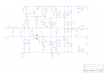
Vr18 is typed wrong.
I can see the imbalance in the output stages and in the LTP.
I suggest two changes.
1.)
Increase the driver current massively. Try doubling by paralleling another 100r across R35. This will make the drivers faster and may require a small change to the existing compensation. If that works and the drivers are still cool enough, then try adding a third 100r for a tripling of driver current.
Note that the output devices are also showing a big difference in hFE. The sinking and sourcing into the driver circuit is not equal.
2.)
Add a trimming resistor across R6. Try 1k0 and remeasure the difference in LTP collector voltages. Estimate what trimmer value will give an exact balance of the LTP emitter currents.
The reason for the imbalance is that Q9 is not sinking the same current as the Q4 cb link and not selecting Q1, 2, 3, 4 for equal Vbe and nearly equal hFE at the operational current and temperature.
Finally,
Check that all the Grounds are connected to the ground trace to the right hand side of the R37 network. No exception, I mean ALL grounds.
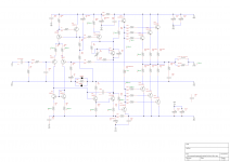
Ranchu32,
I would add a high value resistor (>100 kOhm) connected to ground ahead of C1 to avoid possible big bang in the loudspeaker if, when the amp is on, you connect its input to a source
It is not recommended to plug input connectors when the amp is on because of possible sudden charges or discharges of this capacitor.
My initial blameless had not such a discharging resistor and I once blow up the output stage of one channel for this reason. It's the only failure which ever happened with it.
- Status
- This old topic is closed. If you want to reopen this topic, contact a moderator using the "Report Post" button.
- Home
- Amplifiers
- Solid State
- My Blameless