Go for Mimesis. Jim's Audio sells kits and there is a thread here on this amp.
Hi Speed Power Amplifier SP Protect MOSFET O P Mimesis | eBay
cheers,
Hi Speed Power Amplifier SP Protect MOSFET O P Mimesis | eBay
cheers,
I know you probably want a solid state discrete design amp, but why not consider a LM3886 chipamp? Those rail voltages will give you 50W into an 8R load, so you can at least two and at most four chipamps with 8-ohm loads. The voltages are a little too hot for 4R loads using the LM3886 I am afraid, but you didn't mention load impedance...
Member
Joined 2009
Paid Member
Jim's Audio doesn't always get permission to use a design for his boards so I'd not recommend him. There are other options.
You asked for a schematic so I assume you want to build your own ?
Check out: Greg's Web Site
Also find the thread and group buy on the VSSA amplifier.
You asked for a schematic so I assume you want to build your own ?
Check out: Greg's Web Site
Also find the thread and group buy on the VSSA amplifier.
The Circlophone is a neat little amplifier, tolerant and easy to build (no adjusments or thermal compensations) having a very pleasant sound.All is said in the tittle , i have transformer of 120W 2x26V ACI need schematic for 40w amplifier that will work on +- 36V DC , greetings to all
It is also cheap and effective: it only loses 2V of rail voltage on its output.
http://www.diyaudio.com/forums/soli...-cheap-circlophone.html?highlight=circlophone
You have a wide range of PCBs and builds to choose from:
http://www.diyaudio.com/forums/soli...-beginner-friendly.html?highlight=circlophone
HI,
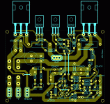
attached is the schematic and PCB of a very simple amp, that meets your requirements, it could do 50W into 8 and 90W into 4 ohm load. though very simple and employ easy to get parts, it sounds really good.
worth trying.
Regards,
Aniket
attached is the schematic and PCB of a very simple amp, that meets your requirements, it could do 50W into 8 and 90W into 4 ohm load. though very simple and employ easy to get parts, it sounds really good.
worth trying.
Regards,
Aniket
Attachments
Hi Daniel,
the transformer enables a 65Watt in 8 Ohms mono amplifier. Two channels is also possible, but that is not ideal... because compression will start at "living-room" sound levels.
Most discrete diy amplifier (kits) allow +/- 25 to 50 volts DC, so selecting one won't be a problem.
Regards, Edwin
the transformer enables a 65Watt in 8 Ohms mono amplifier. Two channels is also possible, but that is not ideal... because compression will start at "living-room" sound levels.
Most discrete diy amplifier (kits) allow +/- 25 to 50 volts DC, so selecting one won't be a problem.
Regards, Edwin
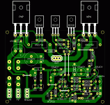
Hi Aniket.
Where are the LEDs on sematic?
thank you
Hello,
The LED's are just for the power indication on the rails. also, corrected some mistakes on the PCB.
Regards,
Aniket
Attachments
Hello Daniel
greetings try this amp 100% tested
warm regards
andrew lebon
Andrew please pull your self together you are posting a circuit that people of the forum and people of the audio left behind almost 100 years ago ???
have you ever heard terms like decoupling , RF input filter , thermal stability, control of Iq versus temperature and darlington stability issues ?
your circuit is 100% tested ? by who ? because if you just say so sorry this will not be enough ...
Posting in the forum is supposed to help each other not to create more trouble ...
The circuit you posted is simply sad ....
amplifier
Ax-11 is good for start.Simple with common parts.
Hi Daniel try any Apex amp.All is said in the tittle , i have transformer of 120W 2x26V AC
Ax-11 is good for start.Simple with common parts.
Daniel if you want you can mail me.I've serveral amp boards you can use
DIY spirit ? basic principal is sharing with each other .....
All is said in the tittle , i have transformer of 120W 2x26V AC
I subscribe to everything ELVEE said. I built the Circlophone and it's a great litlle amp!
Regards,
Ted
One of the simple VSSA versions, like the ones in the PeeCeeBee thread, would fit very well with you proposed power supply.
Try this amplifier it has thumping base
This versatile amplifier circuit is designed and submitted by Mr Seetharaman Subramanian from Chennai . The full credit of this article goes to him and we are very proud to publish this fabulous circuit here.
Seetharaman’s description about the circuit.
This concept has appeared long back in Practical Electronics a UK based Magazine. Based on this concept I designed this circuit during 1981 to 1986 with lots of field trials and modifications, the design was frozen in 1986. I have assembled so many amplifiers for me and for my friends based on this design with various power levels. They are still kicking in so many houses. This concept can be applied to any existing amplifier also. You must listen to believe the crystal clear thumping bass response. crystal clear mid and hi frequencies. Good transient response with very low distortion. Hope you guys will enjoy the reproduction of this amplifier.
In the art of audio sound reproduction it is well-known that the dynamic loudspeaker is more nonlinear and generates more distortion than all the other system components combined. This is particularly true at low frequencies which require large cone excursions where the stiffness of both the inner spider and the outer surround increases rapidly as the cone approaches its peak displacement, resulting in a nonlinear suspension compliance generating high distortion.
For example, in a typical high fidelity sound system at a frequency of about 35 Hz the total harmonic distortion of the amplifier might be of the order of 0.01%, whereas the distortion of the loudspeaker might range from about 3.0% to about 50.0%, depending upon the loudness. If this cone motion can be sensed and given as a feed back to the earlier stage of the amplifier, this distortion can be reduced dramatically.
Motional Feedback (MFB) was a speaker system developed in the early 1970s by Philips Holland. It introduced a feedback system to the woofers of HiFi loudspeakers, enabling them to achieve a more extended low frequency response in a relatively small enclosure. The key benefits are a very controlled bass response. Any distortion induced by the enclosure or the woofer itself is immediately corrected by the feedback. These hand-built speakers were sounding very good and were quite expensive.
As a different approach, instead of using the cone movement, the current flow through the voice can be sensed (the current is proportional to cone movement) and can be used as a cone movement feedback. This novel idea is used in this amplifier design (I don’t claim any originality; this idea has appeared in Practical Electronics UK Magazine – long back – They might have even patented it).
The amplifier used here is a standard Philips audio application circuit, with a specification of 40 Watt RMS @ < 0.06% Total Harmonic Distortion into 8 ohms impedance speaker and having a frequency response from 20Hz to 100 KHz, suitably modified for our application.
The amplifier is a conventional class B directly coupled quasi complimentary out put stage, operating with single 56Volt supply (no need for a regulated or dual power supply). BC157 is the pre-driver and half supply stabilizer. BD 139 is the driver, a BD139 and a BD140 complimentary pair out put driver stage with 2N3055 as final out put stage. The speaker voice coil current is sensed through 0.47 ohms resistance connected from speaker one end to ground. This signal is given as negative fed back to previous stage through 470 ohms. The half supply at speaker coupling capacitor can be adjusted by varying the 39K resistance (if required you may fix a 100K pre set in the place of 39K and adjust for half supply with no in put signal at junction of both 0.47 ohms of out put transistors and speaker coupling capacitor). The quiescent current through output transistors can be adjusted with 22 ohms in series with two bias diodes 1N4007. The value for 50mA quiescent current will lie between 15 to 33 ohms for a supply of 56volts. The amplifier can be protected with a simple 1.5Amp fast acting fuse in the positive power supply.
The amplifier can be assembled on 40watt Philips amplifier application board or on any standard plain straight line board. All the three driver transistors require cooling clips. (Standard TO220 casing cooling fins). Out put transistors require a good quality extruded alloy heat sink with insulating mounting kit and with a smear of silicon conductive grease, for good conductance of heat.
The recently appeared passive Bass/Treble tone control with 12volt supply in “Circuits Today” as Baxendall tone control circuit is the most suitable preamplifier and tone control for this amplifier.
http://www.circuitstoday.com/wp-content/uploads/2010/04/motional-feed-back-amplifier-circuit.png
http://www.circuitstoday.com/wp-con...r-supply-for-motional-feed-back-amplifier.png
- Status
- This old topic is closed. If you want to reopen this topic, contact a moderator using the "Report Post" button.
- Home
- Amplifiers
- Solid State
- Need schematic for 40W Amplifier with good sound quality that works on +-36V DC Max