"You have the array of resistors in parallel (the divider) near the OPS and
only run the divided Voltage back to the NFB point."
It looks like that but they are physically close to the summing junction. The boards are quite small. You have to watch out for capacitance from the feedback junction to ground or across the feedback resistors otherwise you can get gain peaking.
Could you show me an example of an existing layout ??
On a longer board , like mine ... would you run the full OPS signal right to the NFB/"2 resistor "summing junction" ??
PS - to-220 resistor is "gold", Costs $5-10usd.
OS
Last edited:
I won't argue with success  ...
...
Once I get the OPS/Vbe/Regulator section done ,
I will ask whether a modular unit is desired.
Below is the "madness". I did this on an EF2 ... and
actually listened to my schematic collection (20+ amps).
Once I make the OPS - I can cut and paste for both
dedicated full PCB's and modular daughtercards. Smaller card will solder on those
big square pads. OP signal will be right on that center pad (NFB)
OS
...Once I get the OPS/Vbe/Regulator section done ,
I will ask whether a modular unit is desired.
Below is the "madness". I did this on an EF2 ... and
actually listened to my schematic collection (20+ amps).
Once I make the OPS - I can cut and paste for both
dedicated full PCB's and modular daughtercards. Smaller card will solder on those
big square pads. OP signal will be right on that center pad (NFB)
OS
Attachments
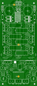
OPS DONE ....
Researched the Halcro , both the HK680/990 , and all the similar layouts
on this forum.
Refined the separation of "dirty" current pulse components and the clean
regulation of the IPS (clean).
Added these features :
1. Boosted rail capability.
2. dual pitch caps (3.5/5mm)
3. Rail augmentation - 14ga wire on top of PCB at the output rails.
4. Aluminum flashing for driver heatsink - no special sourcing. Any
parts will be "hardware store" simple.
5. Feedback return will "float" like a Halcro ! Air is the best insulator.
Standard features :
1. EF3 (triple) with output class driver stage (NJWxxxx).
Built ram tough .
2. 2 device HK680 bias spreader ... the MOST accurate thermal tracking
short of thermal-trak outputs. My 680 will stay within 1 mV ! , regardless
of ambient/amp use.
3. OPS .05% full power distortion in isolation.
4. Diode protected multipliers with large capacitance capability.
Hfe x 470uf @100v (max size C103/106) = 47K "fake" capacitance.
But , we lose 2-3 V on the rails ..... oh well.
5. Main rail caps can be 1000uF @ 80V max.
OPS (this board) numbers start at C/D/Q/R 101 and up and
IPS's (cfa -vfa "front ends") , start at 1 and up.
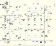
Below is High res. -both PCB and schematic. Dare you to find an
error ....
PS - many , many , many IPS's to use are soon to come !
(CFA-NX is first)
OS
Researched the Halcro , both the HK680/990 , and all the similar layouts
on this forum.
Refined the separation of "dirty" current pulse components and the clean
regulation of the IPS (clean).
Added these features :
1. Boosted rail capability.
2. dual pitch caps (3.5/5mm)
3. Rail augmentation - 14ga wire on top of PCB at the output rails.
4. Aluminum flashing for driver heatsink - no special sourcing. Any
parts will be "hardware store" simple.
5. Feedback return will "float" like a Halcro ! Air is the best insulator.
Standard features :
1. EF3 (triple) with output class driver stage (NJWxxxx).
Built ram tough
.2. 2 device HK680 bias spreader ... the MOST accurate thermal tracking
short of thermal-trak outputs. My 680 will stay within 1 mV ! , regardless
of ambient/amp use.
3. OPS .05% full power distortion in isolation.
4. Diode protected multipliers with large capacitance capability.
Hfe x 470uf @100v (max size C103/106) = 47K "fake" capacitance.
But , we lose 2-3 V on the rails ..... oh well.
5. Main rail caps can be 1000uF @ 80V max.
OPS (this board) numbers start at C/D/Q/R 101 and up and
IPS's (cfa -vfa "front ends") , start at 1 and up.
Below is High res. -both PCB and schematic. Dare you to find an
error ....
PS - many , many , many IPS's to use are soon to come !
(CFA-NX is first)
OS
Attachments
for diy'ers, having an output module wherein options for trying out several types of input sections is indeed nice....
i am sold to the idea of triple EF's, but i believe Technics came out with a quadie EF, have you seen that?
http://www.hifiengine.com/library/technics/se-a100.shtml
i am sold to the idea of triple EF's, but i believe Technics came out with a quadie EF, have you seen that?
http://www.hifiengine.com/library/technics/se-a100.shtml
for diy'ers, having an output module wherein options for trying out several types of input sections is indeed nice....
i am sold to the idea of triple EF's, but i believe Technics came out with a quadie EF, have you seen that?
Technics SE-A100 | Owners Manual, Service Manual, Schematics, Free Download | HiFi Engine
That's a beautiful amp !
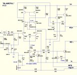
This triple has worst case current gain of ...... 25,000.
Just 60uA VAS load will drive a 2R OP load with 10A.
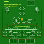
The first in line is the "controversial feed back amplifier" -
I call it the "NX-hawksford" (below).
I also have the Hawksford VAS attached to the "VSSA/Peeceebee".
With the cap multipliers on this OPS board and zeners on the input stage
board , I'm getting much better PSRR/THD than the originals.
For voltage feedback amps , the "badger" does beautiful on this triple ,
doing 10ppm without fancy compensation (TMC). I also have
the luxman 120a and Sansui Z3900 for input stages.
All that needs to be done is to tweak the VAS for 3-6ma current
and plug er' in ....
All the input stage boards use just 12-15ma per rail ... no
heatsinking required ! You might want to thermally couple the VAS
like on the badger just to equalize devices - ALL runs super cool.
One could even SMD a input stage and run LTP's at 1ma with a 3mA
VAS - 30 X 75mm tiny boards.
PS - Bob cordell discussed on "trouble with triples" to have the fastest devices for the drivers - slow predrivers and
slow or equal speed (Ft)outputs. Decouple the driver/predrivers through a resistor (R112/113) ... and one hell
of a stable triple you shall have - I can "splice" anything on this OPS , not the slightest hint of instability!
OS
Attachments
Last edited:
Looks good - I'm looking forward to seeing this sucker!
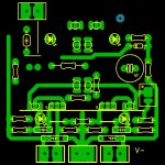
youve managed to get away with single sided boards - I usually give up after an hour and start laying topside tracks. I'll have to be more patient with my next effort.
Thanks . The material on your site was like ESP's but a little "deeper".
Very helpful to get me thinking. I took a couple year break after making
the badger for DIYA and needed a "deep" project to clear out the cobwebs.
This is "round 2" ....and there is no reason a DIY project can not match
or exceed "high end". I know this simple single sided layout will really
kick butt. It IS the best of several high end layouts combined.
Absolutely assured that whatever IPS is "plugged in" will come startlingly
close to it's simulated expectations. (the "badger" did).
I did single sided as I did the badger for prototype purposes. It might even
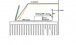
be prudent to leave the NFB return and clean grounds in the atmosphere.
Ha , Ha ... even sheath them in UV reactive teflon with silver wire so
even DIY'ers can have a taste of "classe' "
On to the technical side , this EF3 is a wonderful candidate for
MJL21193/4 OP's or the insane Semitech MG9410/6330 BJT's.
IMAGINE 400-500 watts with just 3 pairs - this board was designed for it !
BTW - These are the IPS's that WILL be posted....
CFA-
1. NX - hawksford
2. VSSA -hawksford
VFA -
3. Sansui -hawksford (gla)
4. Blameless
Something for everyone ....the VFA's have been built and tested already,
they just have a better "home" now.
OS
^+1 here, there was a similar attempt with the Leach amps, too bad it fizzled out...
No "fizzling" here ... If they don't build it yet , they will when they get
a load of the level of the IPS's they can attach. (Or when they see mine.)
Worst case , any successful IPS can be a single (slightly larger) board.
All I have to do is "cut and paste" on to the OPS board after enlarging it.
The OPS is 178mm long when modular , and the full (OPS/IPS) board will be
around 200mm long.
I just put the NAD372 up against the "NX/Hawksford" and my IPS won (in
the simulator). I am quite sure any of my IPS's will "beat the pants" off
of their OEM equivalents
With the "floating NFB" and split grounding ... this will be the "top gun"
for class AB. (below) .. best looking , too (alien look
- UV led hawksford ).Still working on the CFA .... the feedback return layout is critical.
NO high amplitude/current signal will be anywhere near any low level/High Z
signal .. the only "bridge" between these 2 "worlds" will be the NFB
return . (Halcro's Candy did it just this way
).PS- NFB wire goes through the glowing tube ....
OS
Attachments

Last edited:
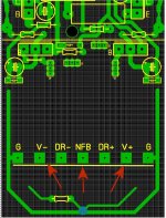
I would take the speaker out and ground exactly where I take the feedback, and if I had a MOSFET relay I would take the feedback after that too, the output coil I would position at the hot speaker terminal.
I did that ... look at the traces. A MOSFET relay would be a good addition.
We want the FB path to be a "straight shot" right to the heart of the IPS
ONLY referencing to the input of L1.
If there is a point I missed , draw me a pix ... I'm game
.OS
The NFB path can not (should
One good way is to put the feedback resistor immediately at the output stage, and run a trace to the resistor to ground.
That trace has a) relatively small signal, about the same as the input signal, and b) is quite low impedance.
So even if the track is relatively long it is very insensitive and has no impact on the surrounding circuitry.
Jan
Yes , that is how I do it on my VFA's (Badger - others). For this one ,
a few different considerations (CFA/VFA - modular).
With a complete OPS/IPS PCB , I would do it exactly like you recommend for
either topology.
With the CFA's , I have 50ma for the NX-H and over 100ma for the VSSA-H
pulsing back through the feedback network. I also will be splicing VFA's onto
this OPS ..... compromise !
My "compromise" is to attach the "floating" full level output wire to the first
resistor in the FB network. This way , I will just have that 1-2V (signal) at
the IPS NFB pad ... the 50-100V signal will be 30mm+ away from the PCB.
If they want to change out IPS's , just un-solder the pad ... pull the resistor/
wire combo out and unscrew the 6 euroblock connections. If anything ...
this thing should be different/cool looking/and a top performer - regardless of
the IPS.
On the technical side of the "rumble" ...
the CFA crowd will have a hard time beating either of my best VFA's -
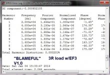
The blame(ful) is WONDERFUL on the triple , 2mhz UGLF , 150v/us slew ,
and low single digit PPM into 3R (below 1/2).
It HAS to have the direct OPS signal back to the IPS (TMC feedback). Otherwise ,
2 feedback paths would have to be created.
... compromise.OS
Attachments
Last edited:
In that case, could we use a small coax for the return fb signal and ground at one end?
Thx-RNMarsh
YES ... I did that on my first 4 pair modular OPS. It worked like a charm.
DO NOT worry , I will give the top CFA my most concerted effort for
perfection - I'm on my 3'rd layout change already. Perfection can't be
rushed.
OS
Attachments
Perfection can't be
rushed.
OS
Agree on that, having the same situation here. Looking to your VFA input stage, no matter what sim is saying, it doesn't stand a chance soundwise against both CFA-s. At least one thing in VFA sch is holding it back, not even speak about the other details. Otherwise good project enabling direct comparison of both VFA/CFA topologies.

- Home
- Amplifiers
- Solid State
- Slewmaster - CFA vs. VFA "Rumble"