Update starting with PCB's
I've made a few changes after several months reading on the forum and other literature (Cordell, Douglas S, Hifisonix...)
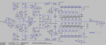
Have look at the schematic please. In the pdf document is some more info and some simulation results.
Any advice/remarks/questions are welcome.
I've made a few changes after several months reading on the forum and other literature (Cordell, Douglas S, Hifisonix...)
Have look at the schematic please. In the pdf document is some more info and some simulation results.
Any advice/remarks/questions are welcome.
Attachments
...Most modern bipolar amps can LTSPICE sim to 0.00005% THD at 200 watts, and maintain this low THD over diverse loads...
The claim does not look plausible to me.
Can you show any reasonable sim with that level of performance?
Best wishes
David
Member
Joined 2009
Paid Member
Any advice/remarks/questions are welcome.
Looks very nice to me.
An alternative, not necessarily better, is to replace the driver FETs with pairs of bipolar transistors in a Sziklai / CFP arrangement like in the Roender amplifier (which I copied into my TGM3 amplifier). The possible benefit is that the two drivers (p-type and n-type) will be better matched than two FETs (n-mos vs p-mos) and yet still provide good isolation between the input stage and bipolar power output stage.
One of my goals was to have relatively high class A power. A cfp performs better with low bias current if I remember correctly.
In my previous amp I noticed much more details in the music when I switched from bjt to FET drivers. FET drivers are a must for me to start with.
Regarding your TGM3 amp, I must admit, it's a total unfamiliar topology for me.
Have you some experience in higher versus lower NFB resistor values, to define a fixed CLG? For example, my shunt NFB resistor is at the moment 221R which is relatively low compared with many other amp's. With 887R which I had first, my UGF was lower than 1Mhz.
Hi
You should have a look to the schematics over there
Parasound HCA-1000A Manual - High Current Power Amplifier - HiFi Engine
Parasound HCA-1200 Manual - High Current Power Amplifier - HiFi Engine
Parasound HCA-1500A Manual - High Current Power Amplifier - HiFi Engine
Parasound HCA-3500 Manual - Ultra High Current Power Amplifier - HiFi Engine
(dynamic bias on the last one)
Thanx J. Curl
Member
Joined 2009
Paid Member
Have you some experience in higher versus lower NFB resistor values, to define a fixed CLG? For example, my shunt NFB resistor is at the moment 221R which is relatively low compared with many other amp's. With 887R which I had first, my UGF was lower than 1Mhz.
I've never done a direct comparison by changing the values in an amplifier without also changing the topology. It's a question that crosses into the CFA vs VFA debate because lower values are usually found with a CFA topology. The lower impedance feedback network often provides greater UGF because there is always parasitic capacitance in the feedback network. But my TGM7 uses an LTP input stage, it is not a low impedance feedback network, but the amplifier has large UGF due to the high feedback factor and it sounds very good.
The claim does not look plausible to me.
Can you show any reasonable sim with that level of performance?
Best wishes
David
Hi David,
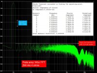
I attached 200W into 4-ohm speaker load LTSPICE simulation output for THD, BW, and FFT. The FFT illustrates that "good" harmonic ratios can be produced with a high-gain plus high-feedback amplifier. The simulation includes LTSPICE models for a regulated driver circuit power supply, and a C-R-C filtered output power supply. I'm collecting parts to get exact sizes for amp+protectionCKT PCB layout and winter construction to fully test the 300 component schematic(160 amp + 140 protection).
There are several low THD amps in the forum.
Attachments
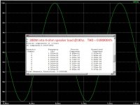
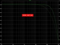
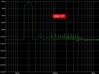
I attached 200W into 4-ohm speaker load LTSPICE simulation output for THD, BW, and FFT...
I quoted from your post where you mentioned only 20 kHz distortion but here you have switched to 1 kHz, which should be very much lower.
Still impressive results if true, but a plot with a header that says "200W Distortion" is not much evidence.
A "reasonable sim" needs a circuit, preferably as an .ASC and realistic models.
If you don't want to reveal your own then a link to any simulation that achieves this performance would be very educational.
...PCB layout and winter construction to fully test the 300 component schematic...
That would be impressive but hardly supports your claim that "most" amps can reach these numbers.
There are several low THD amps in the forum.
I have studied the Edmond Stuart/Ovidiu Poppa amp with interest.
But I am aware of no others that come close to your claim.
Which ones did you mean?
Best wishes
David
I did not want to hijack Bensen’s thread with a new amplifier design, just to show comparison FFTs.
Both the Bensen and Ayre amps use 1Khz 1-2 watt measurement points.
Attached Stereophile’s data for the cult supported Ayre MX-R amp which uses clever symmetrical cascoded FET input circuits driving a ThermalTrak bipolar output stage, and no global negative feedback. Even tube-lover Lynn Olson praises the MX-R.
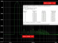
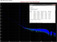
Attached Bensen's FFT sim. "Modest THD, a nice harmonic spectrum using modest feedback, and Fet drivers for more detail to the music compared with bjt's."
Attached LTSPICE sims for a prototype bipolar amp which uses conventional negative feedback. Philosophy = " If you use global feedback use A LOT of it! It is better to significantly beat down ALL THD than to worry if the remaining TINY 3rd/odd harmonics are higher than the remaining TINY 2nd/even harmonics."
Bensen's themes:
How much global negative feedback creates the best sound?
What does the THD(FFT) profile for the ideal solid state amp look like?
Is there an audible difference between FET 2nd order distortion vs. Bipolar odd order distortion?
How much audible distortion and noise does the power supply generate?
Both the Bensen and Ayre amps use 1Khz 1-2 watt measurement points.
Attached Stereophile’s data for the cult supported Ayre MX-R amp which uses clever symmetrical cascoded FET input circuits driving a ThermalTrak bipolar output stage, and no global negative feedback. Even tube-lover Lynn Olson praises the MX-R.
Attached Bensen's FFT sim. "Modest THD, a nice harmonic spectrum using modest feedback, and Fet drivers for more detail to the music compared with bjt's."
Attached LTSPICE sims for a prototype bipolar amp which uses conventional negative feedback. Philosophy = " If you use global feedback use A LOT of it! It is better to significantly beat down ALL THD than to worry if the remaining TINY 3rd/odd harmonics are higher than the remaining TINY 2nd/even harmonics."
Bensen's themes:
How much global negative feedback creates the best sound?
What does the THD(FFT) profile for the ideal solid state amp look like?
Is there an audible difference between FET 2nd order distortion vs. Bipolar odd order distortion?
How much audible distortion and noise does the power supply generate?
Attachments
...Most modern bipolar amps can LTSPICE sim to 0.00005% THD at 200 watts, and maintain this low THD over diverse loads ...
...Attached Stereophile’s data for the cult supported Ayre MX-R amp which uses clever symmetrical cascoded FET input circuits driving a ThermalTrak bipolar output stage, and no global negative feedback. Even tube-lover Lynn Olson praises the MX-R....
The measured performance of this amp is worse than .03% at 200W into 4 ohms, apparently at only 1 kHz. What relevance does this have to your earlier claim of better than .00005% for "most... amps" ?
And to stay on topic.
What model level and values did you and Bensen use to produce the distortion numbers for his amp?
When Toni (ASTX) used the LTSpice model level 3 to simulate a MOS VAS in his amp the simulations were wildly optimistic compared to measured performance.
This is not unexpected, MOSFET models are problematic and almost certainly the cause of the error, because the rest of his simulation has been checked to match measured performance reasonably well.
Best wishes
David
Last edited:
David,
I have used exactly the same model as ASTX for the mosfet. Apparently there is only one model available after a long search. Strange, while the 610/9610 is widely used.
I understand that THD numbers for simulations with mosfet's are far from reality. Personaly I'm not looking for super low THD values. But I hope that the harmonics spectrum looks the same in reality (only higher values), can this be?
After all many A rating amp's at Stereophile have rather high THD numbers!?
...I have used exactly the same model as ASTX for the mosfet. Apparently there is only one model available...
I have posted some information in Toni's thread so I won't repeat it here, but it may be useful.
I understand that THD numbers for simulations with mosfet's are far from reality. Personaly I'm not looking for super low THD values. But I hope that the harmonics spectrum looks the same in reality (only higher values), can this be?
I doubt it and would not rely on it.
I just plan to make ALL distortion components so low that they are inaudible, and then who cares about the relative amounts.
After all many A rating amp's at Stereophile have rather high THD numbers!?
Do they EVER do properly controlled, unbiased tests?
I would like to see one.
Best wishes
David
I did not want to hijack Bensen’s thread with a new amplifier design, just to show comparison FFTs.
Both the Bensen and Ayre amps use 1Khz 1-2 watt measurement points.
Attached Stereophile’s data for the cult supported Ayre MX-R amp which uses clever symmetrical cascoded FET input circuits driving a ThermalTrak bipolar output stage, and no global negative feedback. Even tube-lover Lynn Olson praises the MX-R.
Attached Bensen's FFT sim. "Modest THD, a nice harmonic spectrum using modest feedback, and Fet drivers for more detail to the music compared with bjt's."
Attached LTSPICE sims for a prototype bipolar amp which uses conventional negative feedback. Philosophy = " If you use global feedback use A LOT of it! It is better to significantly beat down ALL THD than to worry if the remaining TINY 3rd/odd harmonics are higher than the remaining TINY 2nd/even harmonics."
Bensen's themes:
How much global negative feedback creates the best sound?
What does the THD(FFT) profile for the ideal solid state amp look like?
Is there an audible difference between FET 2nd order distortion vs. Bipolar odd order distortion?
How much audible distortion and noise does the power supply generate?
Hi
Could you share the Ayre MX-R LTspice too ?
Thanks
I made a mistake above, first I was using the 610/9610 as VAS devices.
Now, I will use the 2SK216/2SJ79 as VAS devices, but cascoded.
Here are the Spice models I've used, found somewhere on this forum.
********** From diyaudio 2011_08
.MODEL bob79 PMOS (LEVEL=1 VTO=-.1 KP=40m GAMMA=18.6
+ PHI=.75 LAMBDA=1.04M RD=.84 RS=.84 IS=250F PB=.8 MJ=.46
+ CBD=862P CBS=1.03N CGSO=57.6N CGDO=48N CGBO=1.09U)
********** From diyaudio 2011_08
.MODEL bob216 NMOS (LEVEL=1 VTO=.1 KP=60M GAMMA=18.6
+ PHI=.75 LAMBDA=521U RD=.84 RS=.84 IS=250F PB=.8 MJ=.46
+ CBD=658P CBS=790P CGSO=26.4N CGDO=22N CGBO=852N)
**********
I just plan to make ALL distortion components so low that they are inaudible, and then who cares about the relative amounts.
David
Well in my previous amp, I did listening tests between several BJT's as drivers (2sc2911/2sa1209 - 4793/1938) and Fet's (216/79). I'm sure the BJT's would have given me lower THD numbers, however I've chosen for the FET's because the transparency (more and sharper details) was so much better.
Do they EVER do properly controlled, unbiased tests?
I would like to see one.
Best wishes
David
Sorry, I don't understand what you mean by that.
Densen,
Power Supply.
Two Boxes: There should be just one Star Ground Point, with separate wires from this Star Ground to each "short" remote Ground PCB trace/tree_trunk. Your box-to-box cable would need several ground wires.
Easy Breadboard: You could start with your wood base power supply and use L-brackets to mount the amplifier heatsinks with attached driver PCB. All amplifier circuits could be put on one PCB attached to the heatsink with spacers. OR The amplifier circuits could be divided into the output PCB circuits and separate driver PCB circuits.
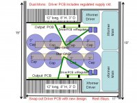
Dual Mono: You could mount your main transformers to the front panel and driver transformers to the side panels in a LEFT - RIGHT dual mono construction. A PCB just for the output transistor components would be mounted on stand-offs onto the heatsink. The regulated power supply for the driver circuits can be on the driver PCB. The output circuit seldom changes. When you design a new amp circuit, only the driver PCB needs to be exchanged.
Mono: A small chassis with a complete power supply for each channel.
Power Supply.
Two Boxes: There should be just one Star Ground Point, with separate wires from this Star Ground to each "short" remote Ground PCB trace/tree_trunk. Your box-to-box cable would need several ground wires.
Easy Breadboard: You could start with your wood base power supply and use L-brackets to mount the amplifier heatsinks with attached driver PCB. All amplifier circuits could be put on one PCB attached to the heatsink with spacers. OR The amplifier circuits could be divided into the output PCB circuits and separate driver PCB circuits.
Dual Mono: You could mount your main transformers to the front panel and driver transformers to the side panels in a LEFT - RIGHT dual mono construction. A PCB just for the output transistor components would be mounted on stand-offs onto the heatsink. The regulated power supply for the driver circuits can be on the driver PCB. The output circuit seldom changes. When you design a new amp circuit, only the driver PCB needs to be exchanged.
Mono: A small chassis with a complete power supply for each channel.
Attachments
Here are the Spice models I've used, found somewhere on this forum.
********** From diyaudio 2011_08
.MODEL bob79 PMOS (LEVEL=1 VTO=-.1 KP=40m GAMMA=18.6
+ PHI=.75 LAMBDA=1.04M RD=.84 RS=.84 IS=250F PB=.8 MJ=.46
+ CBD=862P CBS=1.03N CGSO=57.6N CGDO=48N CGBO=1.09U)
********** From diyaudio 2011_08
.MODEL bob216 NMOS (LEVEL=1 VTO=.1 KP=60M GAMMA=18.6
+ PHI=.75 LAMBDA=521U RD=.84 RS=.84 IS=250F PB=.8 MJ=.46
+ CBD=658P CBS=790P CGSO=26.4N CGDO=22N CGBO=852N)
**********
Level=1 Spice models are, unfortunately, useless for any distortion estimates.
...Sorry, I don't understand what you mean by that.
As far as I know, Stereophile does not rate the products based on unbiased tests, conducted based only on the sound. Instead the products are identified and seen, so people are inevitably influenced by what looks impressive, has a reputation, and costs a lot.
I would like to see a properly conducted test, with the test data.
My first tertiary qualifications were in statistics, a subject that is useful, even if one does not use it professionally. It helps spot B.S., and the Stereophile results look suspicious to me.
Best wishes
David
The Ayre amp is with out a doubt a cult amp - but even Bob Cordell has praised its sound and thats someone who I believe is quite objective.
The only correct way to assess the sound between amplifiers is DBT. I dont trust any human to give an objective opinion in a sighted test - its not because we are all purposefully dishonest, its just the way we are made. However, the hi-fi industry is small, and very interconnected with manufactureres, reveiwers and journalists - they have a symbiotic relationship and make a living selling stuff. We should expect that they will reinforce each others views - this is exactly how business works elsewhere as well.
Looking at the Ayre, you can see the classic low/zero feedback distortion profile which is that hump you see between 1W up until just before the onset of clipping.
The reason for the hump is, starting from low powers, as the VAS and OPS drive harder, their non-linearity rises. At higher powers the curve decreases again because the non-linearity does not get worse as quickly (i.e. it flattens out), and distortion is being expresses as a % of output power. This is quite a feat by the way - most zero/low feedback amps do NOT slope downwards to this extent at higher power - they flatten out, or slope upwards more slowly. At very high powers, it increases again rapidly before going nearly verticle due to clipping. The portion sloping upwards before the onset of clipping may be due to the driver stage exiting class A, and/or loading on VAS/TIS.
I would postulate that this amp sounds fairly clean and consistent up to about half power, and then the high power non-linearity realy kicks in, so the sound character may change at these levels.
Personally, I dont think hitting ppm distortion levels is important . . . wasting parts and effort on this in the hope that it will bring better sound is a false hope. Below 0.1% you arent going to be able to readily hear any distortion - and espcially so if its low order. But, just make sure any distortion you are getting is not from bad engineering practice - noisey suppliers, bad layout, common imepdance coupling, lousy comp etc. There are lots of things you can do right even in the absence of feedback.
An intersting amplifier . . . but, I do prefer designs with feedback")
The only correct way to assess the sound between amplifiers is DBT. I dont trust any human to give an objective opinion in a sighted test - its not because we are all purposefully dishonest, its just the way we are made. However, the hi-fi industry is small, and very interconnected with manufactureres, reveiwers and journalists - they have a symbiotic relationship and make a living selling stuff. We should expect that they will reinforce each others views - this is exactly how business works elsewhere as well.
Looking at the Ayre, you can see the classic low/zero feedback distortion profile which is that hump you see between 1W up until just before the onset of clipping.
The reason for the hump is, starting from low powers, as the VAS and OPS drive harder, their non-linearity rises. At higher powers the curve decreases again because the non-linearity does not get worse as quickly (i.e. it flattens out), and distortion is being expresses as a % of output power. This is quite a feat by the way - most zero/low feedback amps do NOT slope downwards to this extent at higher power - they flatten out, or slope upwards more slowly. At very high powers, it increases again rapidly before going nearly verticle due to clipping. The portion sloping upwards before the onset of clipping may be due to the driver stage exiting class A, and/or loading on VAS/TIS.
I would postulate that this amp sounds fairly clean and consistent up to about half power, and then the high power non-linearity realy kicks in, so the sound character may change at these levels.
Personally, I dont think hitting ppm distortion levels is important . . . wasting parts and effort on this in the hope that it will bring better sound is a false hope. Below 0.1% you arent going to be able to readily hear any distortion - and espcially so if its low order. But, just make sure any distortion you are getting is not from bad engineering practice - noisey suppliers, bad layout, common imepdance coupling, lousy comp etc. There are lots of things you can do right even in the absence of feedback.
An intersting amplifier . . . but, I do prefer designs with feedback
Last edited:
Update: OPS Proto pcb ready
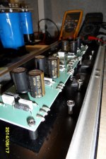
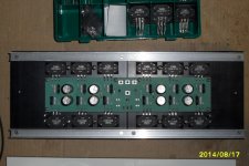
I etched the OPS PCB using the foto transfer method on some old PCB material I have laying around.
The finale heatsinks will normaly be the 165mm x200mm from Modushop. I had some laying around from 150mm x200mm, which are ideal for the prototyping.
Base stoppers (4R46) and Dale emitter resistors (0R22) are all 0.5% types, this to not decrease the mathing specifications of the output transistors.
Decoupling fils cap are Rifa/Evox MMK types.
Electrolytics are Nichicon KZ MUSE
Power supply connection are very close to each other to prevent long wires and to twist them as far as possible. All heavy current connection are done with a print connector with a M3 threaded hole.
The driver emitter resitors will be on this PCB, values (+-15ohm) will be choosen during experimenting with drivers bias. During prototyping I soldered 2 times 4pins on the PCB to easily change these resistors.
Attachments
Last edited:
- Status
- This old topic is closed. If you want to reopen this topic, contact a moderator using the "Report Post" button.
- Home
- Amplifiers
- Solid State
- 2nd amp from scratch: Low NFB- FET front end - BJT OPS