I'm trying to build a relay-switched resistor ladder to form the variable element of a balanced volume control. I need the ladder to have a logarithmic characteristic, and in order to limit the number of relays, I'm trying to adapt a standard logarithmic resistor ladder - in effect to change it from a potential divider into a variable resistor.
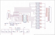
The circuit I have come up with is as follows (this is just an 8-step ladder, but I will add a few more stages when I get it working). I am switching the relays in a Gray's Code sequence, with S3 being the most significant bit.

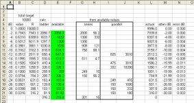
I've built a model in an Excel spreadsheet, and with the resistor values as follows, the circuit almost works:
R1=1k
R2=143R
R3=7.9R
RP=1k
RA=357R
RB=117R
Here is what the spreadsheet looks like:

As you can see, all but two of the resultant resistance values of the network (RL) fit the required response perfectly. It's clear why these two values are so wrong because R3 is so much smaller than RA and RB. Unfortunately I cannot figure out how to make this work.
If anyone has any bright ideas, I would be very grateful!
The circuit I have come up with is as follows (this is just an 8-step ladder, but I will add a few more stages when I get it working). I am switching the relays in a Gray's Code sequence, with S3 being the most significant bit.
I've built a model in an Excel spreadsheet, and with the resistor values as follows, the circuit almost works:
R1=1k
R2=143R
R3=7.9R
RP=1k
RA=357R
RB=117R
Here is what the spreadsheet looks like:
As you can see, all but two of the resultant resistance values of the network (RL) fit the required response perfectly. It's clear why these two values are so wrong because R3 is so much smaller than RA and RB. Unfortunately I cannot figure out how to make this work.
If anyone has any bright ideas, I would be very grateful!
I'm trying to build a relay-switched resistor ladder to form the variable element of a balanced volume control. I need the ladder to have a logarithmic characteristic, and in order to limit the number of relays, I'm trying to adapt a standard logarithmic resistor ladder - in effect to change it from a potential divider into a variable resistor.
The circuit I have come up with is as follows (this is just an 8-step ladder, but I will add a few more stages when I get it working). I am switching the relays in a Gray's Code sequence, with S3 being the most significant bit.
View attachment 387379
I've built a model in an Excel spreadsheet, and with the resistor values as follows, the circuit almost works:
R1=1k
R2=143R
R3=7.9R
RP=1k
RA=357R
RB=117R
Here is what the spreadsheet looks like:
View attachment 387380
As you can see, all but two of the resultant resistance values of the network (RL) fit the required response perfectly. It's clear why these two values are so wrong because R3 is so much smaller than RA and RB. Unfortunately I cannot figure out how to make this work.
If anyone has any bright ideas, I would be very grateful!
I took a different approach and made 2dB steps for a 16 ch relay taped resistor chain.
I decided to only use 2 available values for any single resistance value required.
With this method I need 21 different values to get what I need.
Spreadsheets are great if setup correctly to display what you need.
I am not quite sure I understand how your schematic works...where "RL" connects in the greater scheme of things.
If you have the time send me an e-mail with the full schematic and spreadsheet...I might be able to help.
")
Attachments
Does this help any?
The delta1 Relay-based R-2R Stereo Attenuator, then click the resistor calculator on the left.
The delta1 Relay-based R-2R Stereo Attenuator, then click the resistor calculator on the left.
I don't think that the R-2R approach will work for a balanced control (although it will admirably serve the purpose of replacing a potentiometer in an unbalanced application). Here's the circuit that my logarithmic network is intended to slot into:

The main aim is to use as few relays as possible and minimise the number of microcontroller IO pins that will be needed.
This started out as a simple problem to solve and has become much more of an intellectual challenge!
DUG - I will email you the spreadsheet so that you can play around with it.
The main aim is to use as few relays as possible and minimise the number of microcontroller IO pins that will be needed.
This started out as a simple problem to solve and has become much more of an intellectual challenge!
DUG - I will email you the spreadsheet so that you can play around with it.
Your topology is doomed.
Row 000 dictates the value of RP
Row 001 + fixed RP dictates the value of R1
Row 010 + fixed RP dictates the value of R2
Row 100 + fixed RP dictates the value of R3
Row 011 + fixed RP, R1, R2 dictates the value of RA
Row 110 + fixed RP, R2, R3 dictates the value of RB
That's it; all six degrees of freedom are used up. There is no way to meet the constraints of the other two rows.
I have a hunch that the problem may be easier to solve if you consider the circuit to be a network of switches and conductances, rather than switches and resistances.
...
The main aim is to use as few relays as possible and minimise the number of microcontroller IO pins that will be needed.
...
4 IO lines plus enable (5 total) to control 16 relays.
Enable is so that there is an "all OFF" state before binary 0000 (decoded as 1)
Fed from Arduino Uno
Attachments
I don't think that the R-2R approach will work for a balanced control
I think it will. You just stack them. Instead of one stereo R2R ladder for L&R, you use one stereo R2R per channel.
How about 16 relays and 16 binary-weighted conductances/resistances? Then use a lookup table in uC software to convert from "desired attenuation in dB" into "relay setting".
If you're emulating a GoldPoint or Shinkoh 24-position stepped attenuator, your table will have 24 entries; 96 bytes. Not much at all.
If you're emulating the Mark Levinson No.32 preamp, which has 0.1dB steps from 0dB to -57dB, and then 1.0dB steps from -57dB to -99dB, your table will have 612 entries; 1836 bytes. Still quite acceptable if your uC has got 16 KBytes of flash memory, like in (this $1.89 device)
With a binary weighting scheme and 16 relays, your range of attenuation will be (2^16 to one) , same as the dynamic range of 16 bit compact discs.
Check out Stereophile's review of the ML No.32 (here). Levinson clearly uses 16 relays in their stepped attenuator: "this hardware provides for more than 65,000 steps" and hey, whaddya know, 2^16 equals 65,536. Another example of high school math being useful in our everyday lives.
You need a series of L pads (for unbalanced) or C-pads (for balanced) that use a relay to either bypass the series resistors and disconnect the parallel resistors (SPDT for unbalanced, DPDT for balanced) or include all resistors and form an attenuator with a known input and output impedance. The series of attenuators need to have a binary sequence in dB, say 1, 2, 4, 8, 16 etc dB which will give you a 1dB attenuation resolution.
Although gray code looks very desirable for this application because you avoid major carry problems, there is no solution for a network like this, straight binary has to be used but in your controller, you have to take care of relay contact make/break delays to avoid clicks, also you can stagger relay activation to minimize such problems.
Although gray code looks very desirable for this application because you avoid major carry problems, there is no solution for a network like this, straight binary has to be used but in your controller, you have to take care of relay contact make/break delays to avoid clicks, also you can stagger relay activation to minimize such problems.
Could you please explain what you mean by "L pads" and "C pads" - these are not terms I've heard before.
Maxw - I'm not sure if I understand your suggestion of stacking the R-2R networks? The issue with the balanced control is that the two balanced phases cannot attenuated with a potential divider to ground because this will compromise common-mode rejection. Rather, a proportion of the two phases need to be summed to reduce the signal amplitude. This is why I need an adjustable resistance and not a traditional attentuator network.
Another application I have for the logarithmic network (when I eventually work out how to do it) is for an adjustable cartridge load resistance on my phono stage input. I'll only need 8 steps for this, and am hoping to get away with three relays.
Maxw - I'm not sure if I understand your suggestion of stacking the R-2R networks? The issue with the balanced control is that the two balanced phases cannot attenuated with a potential divider to ground because this will compromise common-mode rejection. Rather, a proportion of the two phases need to be summed to reduce the signal amplitude. This is why I need an adjustable resistance and not a traditional attentuator network.
Here are some other examples...
From The δ1 Relay-based R-2R Stereo Attenuator
"One δ1 board contains two stereo unbalanced channels. You may install up to two δ1 boards per system* to support a stereo balanced configuration. Multiple δ1 and δ2 boards may be "stack-mounted" to reduce their enclosure internal footprint and to simplify wiring."
From Joshua Tree - A Twisted Log Attenuator
"Each relay board can control two single-ended channels (stereo) or a single balanced channel (mono). Signal ground for each channel can be separate or For stereo balanced operation, two relay modules are used."
From 8th note - Stepped attenuator details page
"It is possible to stack more relay boards to a multi channel configuration:
One relay board - for single ended stereo
Two relay boards - for balanced sources"
From Audio Volume Relay Attenuator with IR Control
"Extra relay PCBs allow a multi-channel input select and volume control, for 5.1 or 7.1 sound, or for stereo audio with balanced (XLR) connections."
Thanks for these links. However, if I read them correctly, they are all suggesting using separate attenuator boards for the hot and cold phases in the way that I mentioned in my previous post. This is a bad way to control volume in a balanced circuit because it refers each phase to ground rather than letting them float independently. Because there will always be a tiny but significant difference in the potential division ratio between the two phases, the result is that common-mode rejection is compromised.
...they are all suggesting using separate attenuator boards for the hot and cold phases...
That is not my impression. For example, look at the picture on page 14 of this doc.
There is also some discussion here, quoting Russ (who designed the JT attenuator) "Use one JT relay board per channel. Both + and -."
Hope that helps
I used to propose this style of attenuator for a balanced impedance connection......................... Here's the circuit that my logarithmic network is intended to slot into:
View attachment 387423 ...................
That is until D.Self pointed out that it introduces a "fault" in the way it handles interference. I think the explanation is in his website.
I don't think that the R-2R approach will work for a balanced control (although it will admirably serve the purpose of replacing a potentiometer in an unbalanced application). Here's the circuit that my logarithmic network is intended to slot into:
View attachment 387423
A C-pad or C attenuator is actually the circuit you reference in your attachment. The circuit as drawn assumes a perfectly balanced sugnal and foes not have a ground tap in the midde of the variable resistor.
An L-pad or L-attenuator is half of the complete circuit, a series resistor from the input to output, and a parallel resistor from output to ground.
Before going further into the topic of how to make this into a relay switched stepped attenuator, let me say that a classic R-2R network has a fixed impedance and it's a LINEAR attenuator, not a log one. Replacing the R-2R rule with a different one results in varying impedances as seen from the input or output.
A series of C-pads which can be individually bypassed can be used to construct a relay switched attenuator, by wiring the relays so that the C-pad is either in circuit or not. The attenuation of each C-pad is then set up in a binary exponential series - K*2^(n-1) where n goes from 1 to the number of stages and K is the minimum step of attenuation. The maximum attenuation is then K*2^(number of stages - 1).
Here is an example:
If we want 1dB resolution, then 6 stages will gives us a maximum attenuation of -63dB and the stages themselves have an attenuation of 1, 2, 4, 8, 16 and 32dB. One more stage will get -127dB attenuation and double the number of steps. You might chose to limit the actual number of steps at user disposal in software. As you can surmise yourself, I am sure, the relays which engage the attenuator sections are driven in a simple binary code corresponding to the attenuation level desired.
The attenuators themselves are constructed like this (forgive the description, i don't have means to draw a pic at the moment):
Take you basic C-pad schematic, it has two series resistors from input to output (one each in the + and - leg) and a common parallel resistor.
For each attenuation stage you need one DPDT relay.
For each leg, one common pin of the relay is connected to the output, the corresponding normally closed contact is connected to the input (thus bypassing the series resistor when the relay is not energized), and the corresponding normally open contact is connected to the parallel resistor side for that leg (thus disconnecting the parallel resistor from the circuit).
As you can see, when the relay is not energized, the series resistor is bypassed and the parallel resistor is disconnected, rendering that stage of the attenuator a simple wire from input to output on both the + and - leg. When the relay is energized, the series resistor is no longer bypassed and is now between the input and the output, and also, the parallel resistor is now connected between the + and - output legs, and thus an attenuator is formed.
Knowing the terminating resistance (input impedance of the amp etc) it is not difficult to calculate the value of the resistors in the attenuator stage so that looking from the input the impedance remains exactly the same - this is crucial for proper operation in the series of attenuators as each subsequent attenuator stage relies on seeing a constant impedance on it's output - without this the impedance would vary depending on which attenuator stages were in or out of circuit.
For practical purposes it is actually more appropriate to wire the relay so that the attenuator is engaged when there is no voltage on the coil to avoid unwanted signals at power up or power down, and then use negative logic to switch the relays.
Also, although only one NO contact is absolutely required for the parallel resistor (the other side can be permanently connected), both must obviously be connected if the parallel resistor is center tapped (and the tap connected to ground). Also, there is an advantage to connecting both NO contacts of the DPDT relay, one to each side of the parallel resistor if there is no center tap as this reduces by half the capacitance in series with the parallel resistor, that are actually the capacitances of the open relay contact. Although this is very small, it's effect may become signifficant at high frequencies and when the attenuator as a whole must have a high impedance.
Last edited:
- Status
- This old topic is closed. If you want to reopen this topic, contact a moderator using the "Report Post" button.
- Home
- Amplifiers
- Solid State
- Relay-Switched Balanced Volume Control