Member
Joined 2009
Paid Member
So, the ask is a schematic aimed at 35+35vdc rail voltage. Well, I happen to have a lot of on-hand materials for that size, ready to go.
I ran the simulation file with +/-35v power rails. I didn't see any obvious issues with the as-built schematic. The VAS current will be a bit lower but I feel it's still in a good range for the amplifier.
Of course, there is a zener diode in the dc protection circuit that must be sized so that it conducts at 5V or so below the rail voltage. With 35V rails this zener wants to be somewhere between 18V and 30V - I don't think the exact value is critical. If it's sized at 36V then it won't allow the dc-protect circuit to turn-on the output relay and the speakers will remain unconnected.
I've attached the simulation of the amplifier-only with the lower rail voltage. I'd say proceed to build ! .... let me know if there are issues and I'll try to help.
By the way - I have considered making a specific headphone amplifier based on TGM8, although not anytime soon. But if your experiences are positive I might be interested to explore this with you in the future.
Also.... 'mjona' Michael has been looking at options for further tweaking of the amplifier, especially around the values of the compensation components and I just haven't had time to follow up on yet although it looks really interesting.
Attachments
Last edited:
Member
Joined 2009
Paid Member
I'd like to omit the supply CRC on board and use existing PSU. Similar 10000uF caps but will lose CRC.
Any recommendations for wiring etc. considering external smoothing caps?
thanks
There's a potential benefit from keeping the capacitance on-board - it places reservoir capacity very close to the power devices via low inductance and low resistance connection.
Could this be important for the good bass performance ? - I don't know because I haven't compared with and without on-board capacitors but I suspect it's an important contributor. Are these caps also important for local decoupling as part of good amplifier power rail behaviour ? - I never saw a good amplifier without them.
There is nothing stopping you from installing the on-board caps and also using an existing PSU.
You can also install shorting links in place of the 'R' in the on-board CRC so that you have just a local capacitance. You could then choose to install just the last 'C' or install all capacitors but at half the value as they would be shorter and lighter wight. You could also just install the last 'C' and put shorting links in place of the first 'CR'.
Bottom line - I would keep a decent level of capacitance on-board. Final approach is up to you, it's 'DIY'
")
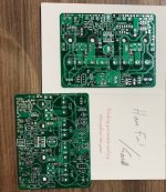
Thanks Bigun. Boards have arrived.

Last edited:
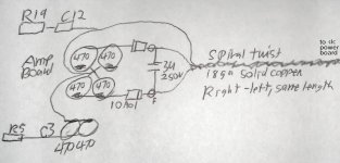
To relocate the big caps but keep similar features, it is possible fill the amp board power cap spots with 470u and short the R. You get 470u||470u per each rail at the amp board. Then series diodes which replaced the R have only one pin in the board (they're at v+ and v-, series to the cord). At the free end of the 10A01 diodes goes the one 250v rail to rail cap (range 2u to 4u7) and the DC power cable. I might add one knot or two ferrites.
Actually I've a plan to use 270u||270u per rail but otherwise exactly like this example. That and 8" (or a little more) of spiral twist thermostat wire (the rail to rail cap puts HF load on dc cable, so perhaps not romex). 18awg solid copper works, or for longer cable, 16awg solid copper works. It must be solid copper, not stranded, because your signal makes trips to the power board and you want just one copy. And, the left and right cables have to be the same length (especially the 0v). A bit of detail pays off when everything else is easier.
This should sound rather similar, as it will block crosstalk just as well. So for small signal crc, use a resistor (loss is a percentage); but, for whole power amp crc, use a diode (loss is a fixed amount) and notice the bass power difference.
Another mention, the doodads and detail are for: move the caps but keep the features.
That's all I've got for now.
Last edited:
Member
Joined 2009
Paid Member
Is this sketch right, or did I get C3 backwards?
Hi - I'm a bit slow today! - what are showing me with this diagram ?
Member
Joined 2009
Paid Member
Hi Gareth
You've said here that "the speaker disconnect circuit is mostly to stop turn on and turn off noises". Is it same with TGM8 protection circuit?
thanks
My intention was to 3 things
a) protection for speaker in case of dc fault
b) delayed turn on to prevent turn on bump associated with singleton input etc.
c) fast turn off before rails collapse to avoid turn off noises
The circuit on the board does all 3 things. However, I have not tested the dc speaker protection to destruction, or under worse case conditions. What I did was to connect it to a cheap speaker and manually increase the dc at the output (provided input signal with input capacitor out of circuit) from zero with higher and higher voltage until the TGM8 SS relay circuit cut-off - this worked just fine but it's not a worse case scenario. I know the circuit could be made more robust by adding more sophistication but so far I didn't have a need. If I make a 500W version I will redesign the protection and likely add short-circuit output protection too. But I didn't find a reason to make a 500W version yet.
Last edited:
Member
Joined 2009
Paid Member
yes, certainly can if you want to, giving you 940uF per rail of on-board capacitance as you mentioned.To relocate the big caps but keep similar features, it is possible fill the amp board power cap spots with 470u and short the R. You get 470u||470u per each rail at the amp board.
I think I’m getting what you are saying now that I cross-reference to your diagram. You will have a 2u to 4u7 off-board cap going from rail to rail and you connect to the board via series diodes. Well, I can’t see at first why this arrangement, i.e. what it will improve, but it sounds like you’ve given this some thought and I don't see any harm in it - why not give it go indeed.Then series diodes which replaced the R have only one pin in the board (they're at v+ and v-, series to the cord). At the free end of the 10A01 diodes goes the one 250v rail to rail cap (range 2u to 4u7) and the DC power cable. I might add one knot or two ferrites.
And C3 was the wrong way around (see post 645) when I built it, the as-built schematic shows how I built it and then I later corrected my build. You should connect the +Ve terminal of C3 to ground, the -Ve terminal to the junction of R5 and R12. Or use a bipolar type - I like bipolar electrolytics a lot.Is this sketch right, or did I get C3 backwards?
Last edited:
Ok, thanks for clarifying. I will add crowbar protection.My intention was to 3 things
a) protection for speaker in case of dc fault
b) delayed turn on to prevent turn on bump associated with singleton input etc.
c) fast turn off before rails collapse to avoid turn off noises
The circuit on the board does all 3 things. However, I have not tested the dc speaker protection to destruction, or under worse case conditions. What I did was to connect it to a cheap speaker and manually increase the dc at the output (provided input signal with input capacitor out of circuit) from zero with higher and higher voltage until the TGM8 SS relay circuit cut-off - this worked just fine but it's not a worse case scenario. I know the circuit could be made more robust by adding more sophistication but so far I didn't have a need. If I make a 500W version I will redesign the protection and likely add short-circuit output protection too. But I didn't find a reason to make a 500W version yet.
The old faithfuls have sentimental value as they remind me of my younger days. Lately I replaced the tweeters for third time as our 3y little son predictably pushed them in and destroyed one dome. It has been some 17 years from the last time I did that... time flies. Anyway, that and the repair of my old amp got me interested again. Having kids in middle age has some good impact.
Member
Joined 2009
Paid Member
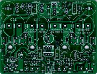
I have finally started my build of the TGM8 but now need to check a few things:
R35 is shown on the schemaic as 4K7 but is 1K on the BOM, which is correct?
R39 is shown on the schemaic as 750R but is 1K on the BOM, which is correct?
Should C25 be fitted? If so, is the correct value 10uF?
D5 is Vs -5V. My supplies are 40V, but I bought a 30V zener (as per the BOM). Is this OK to use? (I assume this is an under-voltage lockout for the protection FETs, so 10V lower than the supply should be OK).
Thanks, Dave
Member
Joined 2009
Paid Member
Hi Dave can you confirm which schematic and which BOM you were comparing because I thought I had gone through and cleaned it up not too long ago (post 1008). The Zener diode is perfect at 30 V.
I recommend installing C25. I didn’t listen with and without C25 to find out if it is super critical but a larger value is better since this means lower impedance; something in the range of 10 to 20 µF will be fine. This cap is designed to shunt the noise of the Zener diode.
I recommend installing C25. I didn’t listen with and without C25 to find out if it is super critical but a larger value is better since this means lower impedance; something in the range of 10 to 20 µF will be fine. This cap is designed to shunt the noise of the Zener diode.
Last edited:
Member
Joined 2009
Paid Member
Darn. unfortunately I’m on travel in Asia and don’t have access to my computer so I won’t be able to upload something better until I’m back. several other people have constructed the amplifier perhaps somebody else can jump in and remind us of the specifications for C25, the size in particular. or search back through the thread and check one of the earlier BOM‘s for the size clearly the voltage only needs to be 16 V or higher. However, you can certainly build the amp without C25 and install it later.
And as for those resistors, defer to the schematic in post 604.
And as for those resistors, defer to the schematic in post 604.
Hi Gareth, I used the latest BOM as in post 1008. Plz note that C25 is not listed, as far as I can see.
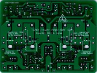
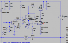
The schematic I used is from post #604:
Aug 20th 2014. Rev B
Is there a later schematic?
Dave,
From a BOM dated July 1, 2014, C25 is 10uF 25V Samsung X7R. In my TGM8 builds, I used Digikey part 1276-1807-1-ND (Samsung CL32B106KAJNNNE).
Looks like D8 is not in the BOM either.
That appears in the attachment to post 96 on page 10 in version TMG8v3-1. This was changed in post 121 on page 13 where the string of three 12V zeners was replaced by a single 47 V zener labelled D5.
You would need to scrutinise the thread to check for updates subsequent TM8v3-2 to reconcile whatever differences there may have been.
The latest pcb's are shown on post 1007 on page 101. If you have older pcb's that are not compatible with updates to the protection you might consider a conventional relay delay and reliance of rail fuses - with +/- 40 Volt supply rails you should be safely within the SOAR of the power transistors.
Earlier this year I drew up a Tian probe plot .asc file for the latest version TMG8v5. I will discuss this in a fresh post.
Attachments
- Home
- Amplifiers
- Solid State
- TGM8 - my best amplifier, incredible bass, clear highs, no fatigue (inspired by Rod Elliot P3a)