This Thread exist already and is closed:
Jeff Rowland Coherence One Schematic - diyAudio
I want to have the schematics of this discrete jFET operational amplifiers:
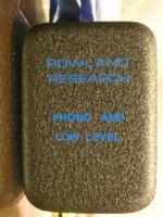
1) Phono Amp Low Level
2) Phono Amp High Level
3) LINE AMP INVERTING
4) Line Amp NON inverting
Who can help?
The modules are similar to those from JC-2 (John Curl, Mark Levinson)
JC-2(220V仕様) Mark Levinson - HiFi-Do McIntosh/JBL/audio-technica/Jeff Rowland/Accuphase
Schematic of the main- and front board/power supply are in post #71 (page 8) under
Jeff Rowland Coherence 1 - Schematic for the Modules wanted
Jeff Rowland Coherence One Schematic - diyAudio
I want to have the schematics of this discrete jFET operational amplifiers:
1) Phono Amp Low Level
2) Phono Amp High Level
3) LINE AMP INVERTING
4) Line Amp NON inverting
Who can help?
The modules are similar to those from JC-2 (John Curl, Mark Levinson)
JC-2(220V仕様) Mark Levinson - HiFi-Do McIntosh/JBL/audio-technica/Jeff Rowland/Accuphase
Schematic of the main- and front board/power supply are in post #71 (page 8) under
Jeff Rowland Coherence 1 - Schematic for the Modules wanted
Attachments
Last edited:
Questions to the Operational Amplifiers used for Offset Servos
A friend of me purchased two preamplifier devices of this model.
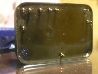
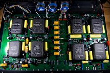
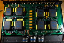
he send me an inside image from both devices - go to the attached pics.
I miss the operational amplifier ICs (DIP-8) - instead this I discover only the 8-pin sockets without the ICs - except by the second device - there are two OP-Amps in the area for the inverting line amps.
according the simplified schematics there are drawed offset servo OP-Amps for each module (four/each channel).
Follow question rises up:
In which cases are the offset servos in use and in which cases
they are dispensable?
Thank you for advices.
P.S.
To the same model there are also this thread:
http://www.diyaudio.com/forums/pass-labs/228183-jrdg-coherence-one-series-i-ii-powersupply.html
A friend of me purchased two preamplifier devices of this model.
he send me an inside image from both devices - go to the attached pics.
I miss the operational amplifier ICs (DIP-8) - instead this I discover only the 8-pin sockets without the ICs - except by the second device - there are two OP-Amps in the area for the inverting line amps.
according the simplified schematics there are drawed offset servo OP-Amps for each module (four/each channel).
Follow question rises up:
In which cases are the offset servos in use and in which cases
they are dispensable?
Thank you for advices.
P.S.
To the same model there are also this thread:
http://www.diyaudio.com/forums/pass-labs/228183-jrdg-coherence-one-series-i-ii-powersupply.html
Attachments
Last edited:
Sorry, cannot really help but fwiw i once deconstructed a similar module. Took me a few days and wasn't any fun. And in the end - where there should have been a zero feedback circuit - 4 cheap opamps were found and nothing else worth concealing.
I wouldn't be too surprised if under the epoxy lies one of John Curl's circuits.
I wouldn't be too surprised if under the epoxy lies one of John Curl's circuits.
In which cases are the offset servos in use and in which cases they are dispensable?
That was one of the highlights of the improved Coherence One, no DC-servos, the transimpy circuit of the Series II modules could do without.
(LNRDS and Stereoplay had articles on the JRDG Coherence One SII, omission of the servo was mentioned in one of them)
Coherence One 1st series has a 411 crud for every module installed.
All series II versions have empty opamp sockets. In case a module turned stray dog as it became older, an opamp could be installed as service patch.
Last version of the SII had no DIP8 sockets soldered to the main board at all, empty landing pads.
Jeff likely figured he could kill two birds with one stone : save a buck, and possibly sell an extra gain module. There's economics for ya !
Sent ramallo a while ago an article [pdf] on it. One page shows schematics with some detail. I'll send if you like to have it.This Thread exist already and is closed:
http://www.diyaudio.com/forums/solid-state/199705-jeff-rowland-coherence-one-schematic.html
I want to have the schematics of this discrete jFET operational amplifiers:
1) Phono Amp Low Level
2) Phono Amp High Level
3) LINE AMP INVERTING
4) Line Amp NON inverting
Who can help?
The modules are similar to those from JC-2 (John Curl, Mark Levinson)
JC-2(220V»ÅÍÍ¡Ë Mark Levinson HiFi-Do McIntosh/JBL/audio-technica/Jeff Rowland/Accuphase
Best regards.
...
The modules are similar to those from JC-2 (John Curl, Mark Levinson)...
The only similarity is that they are potted. Anything else (size, pinout, look and
most likely the circuit too) are different.
I dont think John Curl has ever worked for Jeff Rowland.
Good idea - thank you.Sent ramallo a while ago an article [pdf] on it. One page shows schematics with some detail. I'll send if you like to have it.
Best regards.
my email address: kirschner-hifi@tiefbasswiedergabe.de
I haven't measure offsets, because the devices showed in post #2 I will get next year at the earliest. At which modules you have the mentioned offset with 5VDC ?I couldn't get all the schematic, I got all except the modules (by the moment) (If I'll can get it I publish it for sure
).
I have a question: have you any offset on the output?, my unit have 5 volts and I couldn't find the failure
Thank you for your explanations. Just for such cases a detailled schematic, documentation and Service-Manual isThat was one of the highlights of the improved Coherence One, no DC-servos, the transimpy circuit of the Series II modules could do without.
(LNRDS and Stereoplay had articles on the JRDG Coherence One SII, omission of the servo was mentioned in one of them)
Coherence One 1st series has a 411 crud for every module installed.
All series II versions have empty opamp sockets. In case a module turned stray dog as it became older, an opamp could be installed as service patch.
Last version of the SII had no DIP8 sockets soldered to the main board at all, empty landing pads.
Jeff likely figured he could kill two birds with one stone : save a buck, and possibly sell an extra gain module. There's economics for ya !
indispensable. Unfortunately it isn't available, maybe therefore because it don't exist in the wished kind as by the most typical small high end audio companies usual.
The schematic, I did have in the mean time, is a disaster concerning the clarity. No component values and no internal circuit diagram from the modules. Thus no circuit description resp. understanding possible.
I think "411" means the LF411
http://www.ti.com/lit/gpn/lf411-n
The abbreviation "LNRDS" I had never heard before
Last edited:
La Nouvelle Revue Du Son (in France, it's common to abbreviate it to NRDS)
Jacco, did you used that signature before? I used that sentence in one my answer, in other thread,recently.
Sent ramallo a while ago an article [pdf] on it. One page shows schematics with some detail. I'll send if you like to have it.
Best regards.
https://dl.dropboxusercontent.com/u/28779319/Coherence1001.pdf
The circuit is an extremely sketchy depiction of the power amp - nothing of the pre. There are already detailed circuits of the various Model 7 variants on this board.
The circuit is an extremely sketchy depiction of the power amp - nothing of the pre. There are already detailed circuits of the various Model 7 variants on this board.
The pre is the fig1
hello ramallo. Jeff Rowland is part of Jeff Rowland Design Group [from Google]. Most probably you've checked out his site; it talks about a new and improved Coherence One(s) using SMDs. Has its owner manual; but not a service manual. Rowland is also on Linkedin, and most probably on twitter,and facebook to connect with.
and maybe here on diyaudio, but certainly not with his own name (like X-pro e. g.).hello ramallo. Jeff Rowland is part of Jeff Rowland Design Group [from Google]. Most probably you've checked out his site; it talks about a new and improved Coherence One(s) using SMDs. Has its owner manual; but not a service manual. Rowland is also on Linkedin, and most probably on twitter and facebook to connect with.
Sent Mr. Rowland an Email inquiring about the service manual for the Coherence One Preamplifier.and maybe here on diyaudio, but certainly not with his own name (like X-pro e. g.).
Sent Mr. Rowland an Email inquiring about the service manual for the Coherence One Preamplifier.
Yes, this will be the best solution.
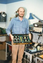
In the attachment some pictures from earlier days and from High End May 2011 Munich.
Attachments


Last edited:
The article is it. Schematics are confidential and are not distributed. I was directed by its market manager to the owner's manual of the new preamp which is void of schematics.Yes, this will be the best solution.
In the attachment some pictures from earlier days and from High End May 2011 Munich.
Best regards
Various Ambient Temperatures and various gain by different Preamps of this model
But now more questions:
1) some parts of the external power supply envelopes of this models goes very hot and other remains cold.
What could be therefore the reason? Maybe because the current consumption of the modules depends on the year of manufacturing?
2) The voltage gain factor of the preamp is different by the same configuration of jumper. Are there in the modules also different parts for the feedback resp. gain determination?
A detailed schematic diagram of all exist variantes from the modules would be very helpful.
By currently models, but not from this old stuff. In the meantime I have heard, that the only reason for the not available schematics would be the fact, that there are only hand-sketched drawings present, and unfortunately very hard to find in the very large quantities of the archived documents.The article is it. Schematics are confidential and are not distributed. I was directed by its market manager to the owner's manual of the new preamp which is void of schematics.
Best regards
But now more questions:
1) some parts of the external power supply envelopes of this models goes very hot and other remains cold.
What could be therefore the reason? Maybe because the current consumption of the modules depends on the year of manufacturing?
2) The voltage gain factor of the preamp is different by the same configuration of jumper. Are there in the modules also different parts for the feedback resp. gain determination?
A detailed schematic diagram of all exist variantes from the modules would be very helpful.
Last edited:
- Home
- Amplifiers
- Solid State
- Jeff Rowland Coherence 1 - Schematic for the Modules wanted