GLA survivor
Hello jpc2001
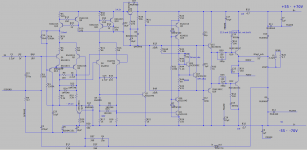
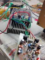
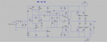
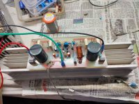
greetings is it possible to help me i have built this driver stage
the bias preset does not work what is the function of C20 33pf
from base to collector on Q22 biasing transistor GLASUI H is
working except for this problem my DC supply rails are +/- 30
DC.
warm regards
Andrew
Hello jpc2001
greetings is it possible to help me i have built this driver stage
the bias preset does not work what is the function of C20 33pf
from base to collector on Q22 biasing transistor GLASUI H is
working except for this problem my DC supply rails are +/- 30
DC.
warm regards
Andrew
Attachments
Hi Andrew
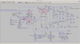
IIRC there was either some local oscillation on the sim, or more likely convergence issues, and C20 fixed that. So I left it in for the real build. It may not be necessary in the real circuit though.
It's hard to debug over the internet.... so the symptom is a 0 bias current at the outputs? I guess it's time to probe voltages around the bias spreader. Hard to guess what could be wrong. An open circuit near R45 or R46 would do it. If the 22uF cap were installed reversed, it might short out and you'd get no bias. Hard to say.
I hate probing live circuits, even after all these years. If you have a dim bulb tester, that makes it safer. For you and the circuit.
You could also test the driver board by itself without the outputs or ballast resistors connected. Tie one of the driver emitters to the feedback rail to close the feedback loop. There's no load connected for this test. Then you can power it up with some resistors in series with the B+ and B- leads to the driver board. (330's might work, something in that range usually.) If anything shorts when you're probing there's no damage. And you can take your time and relax while finding the faults, you don't have to panic about whether leaving it powered up for too many consecutive seconds is going to smoke something. You could still expect to see the expected bias voltage appear across R34.
But you probably knew that!
Sansui 4900Z
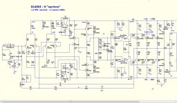
This post is about the Sansui 4900Z, grandparent of the GLASUI.
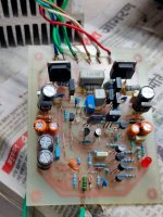
I "sourced" a vintage heirloom Sansui 4900Z receiver on Craigslist. In need of repair, one channel out. This "survivor" is playing again now. It smells like the '70s -- Tobacco City.
There's no output relay, but no click or pop at power on or off.
The amp is very quiet, even driving headphones.
There's no separate preamp to worry about; tone controls are in the power-amp feedback loop. The power amp's input looks into the wiper of the 50k volume pot where it sees variable impedance up to 25k. Both the bass and treble pots have a center defeat position which lifts the wiper off the track. (Don't you wish you could get ALPS to fab up any pot or switch you could dream of?)
The "loudness" control is surprisingly usable, not over-exaggerated.
Modifications
I've attached a spice model of the circuit after the minor mods described here.
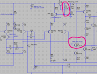
The factory used an enormous 47pF lead cap (C11). This value pushes the ULGF to near 10MHz, and is not ideal for gain margin or phase margin which are both poor. If you only change one thing about your 3900Z / 4900Z / 5900Z, it should be this cap. Values in the 5pF to 10pF range produce ample gain and phase margin without reducing in-band loopgain.
In the factory circuit, the VAS transistors at Q6 and Q7 dissipate around 400mW. But they are TO-92s -- these would run HOT! In fact one of them was dead: Q6 was open in the dead channel. Maybe it failed first from heat, then took out the outputs. Who knows.
To reduce heat dissipation and improve loopgain, you can:
That also boosts the in-band loopgain from ~42dB to ~55dB at 20kHz. The modded circuit simulates around -97dB distortion floor, falling to around -90dB with the volume pot at worst-case -6dB position where the source impedance is 25k.
It's too bad that Sansui doesn't use a zener to regulate the voltage that Q16 supplies to the front end. This makes the circuit more difficult to model and to modify: changing the amount of current that the front-end draws changes its supply voltage, and vice versa. Small changes in wall AC voltage lead to changes in the frontend supply voltage, lead to changes in the VAS current, lead to changes in the loopgain plot and stability margins. Ewww. But Sansui saved 15 cents.
The Inexplicable
I have no idea what transistor Q15 is supposed to do. It looks like it might have a muting function, but neither simulation nor the real circuit suggests it's needed to reduce power-on or power-off noises.
Q15 hurst distortion performance badly, by 25dB in sim. Spice could be wrong: this transistor is reverse-biased when the amp is playing, in a region that spice may not model well. But it seems like a bad idea to have the high-impedance input node looking into the emitter of a BJT not involved in the signal chain. So I deleted it to ensure it doesn't affect distortion performance, which doesn't seem to cause any trouble.
This post is about the Sansui 4900Z, grandparent of the GLASUI.
I "sourced" a vintage heirloom Sansui 4900Z receiver on Craigslist. In need of repair, one channel out. This "survivor" is playing again now. It smells like the '70s -- Tobacco City.
There's no output relay, but no click or pop at power on or off.
The amp is very quiet, even driving headphones.
There's no separate preamp to worry about; tone controls are in the power-amp feedback loop. The power amp's input looks into the wiper of the 50k volume pot where it sees variable impedance up to 25k. Both the bass and treble pots have a center defeat position which lifts the wiper off the track. (Don't you wish you could get ALPS to fab up any pot or switch you could dream of?)
The "loudness" control is surprisingly usable, not over-exaggerated.
Modifications
I've attached a spice model of the circuit after the minor mods described here.
The factory used an enormous 47pF lead cap (C11). This value pushes the ULGF to near 10MHz, and is not ideal for gain margin or phase margin which are both poor. If you only change one thing about your 3900Z / 4900Z / 5900Z, it should be this cap. Values in the 5pF to 10pF range produce ample gain and phase margin without reducing in-band loopgain.
In the factory circuit, the VAS transistors at Q6 and Q7 dissipate around 400mW. But they are TO-92s -- these would run HOT! In fact one of them was dead: Q6 was open in the dead channel. Maybe it failed first from heat, then took out the outputs. Who knows.
To reduce heat dissipation and improve loopgain, you can:
- replace R11 and R12 with 68 ohms. (This is the emitter degeneration for the 2nd stage.)
- replace R21 with 390k ohms. (This is the "lag" resistor from VAS output to ground.)
- replace R13 with 12k ohms. 10k would probably work too. This is the current source for the 2nd stage, and reducing its current reduces the VAS current and reduces power dissipation at Q6 and Q7 to walk it back from the hairy edge of safety.
That also boosts the in-band loopgain from ~42dB to ~55dB at 20kHz. The modded circuit simulates around -97dB distortion floor, falling to around -90dB with the volume pot at worst-case -6dB position where the source impedance is 25k.
It's too bad that Sansui doesn't use a zener to regulate the voltage that Q16 supplies to the front end. This makes the circuit more difficult to model and to modify: changing the amount of current that the front-end draws changes its supply voltage, and vice versa. Small changes in wall AC voltage lead to changes in the frontend supply voltage, lead to changes in the VAS current, lead to changes in the loopgain plot and stability margins. Ewww. But Sansui saved 15 cents.
The Inexplicable
I have no idea what transistor Q15 is supposed to do. It looks like it might have a muting function, but neither simulation nor the real circuit suggests it's needed to reduce power-on or power-off noises.
Q15 hurst distortion performance badly, by 25dB in sim. Spice could be wrong: this transistor is reverse-biased when the amp is playing, in a region that spice may not model well. But it seems like a bad idea to have the high-impedance input node looking into the emitter of a BJT not involved in the signal chain. So I deleted it to ensure it doesn't affect distortion performance, which doesn't seem to cause any trouble.
Attachments
Last edited:
I thought the 4900Z sounded tinny. Playing a square wave on the scope confirms it: "tone defeat" is bass shy. To get a flat response you must set the bass knob somewhere to the right of center.
The sim shows that the low four octaves are cut by ~0.6db with the tone network defeated.
To fix, change RJ12 in the tone network from 6.8K to a series 5.6K + 330ohm. That gets the simulated response level to within 0.1db.
The sim shows that the low four octaves are cut by ~0.6db with the tone network defeated.
To fix, change RJ12 in the tone network from 6.8K to a series 5.6K + 330ohm. That gets the simulated response level to within 0.1db.
Presenting the "Sansui 4900Z-MAX"
Evidently, Sansui had some crackerjack engineer(s?) who came up with the basic circuit, and then turned it over to their "B team" to modify it for a cost-reduced, export-market-only stereo receiver.
So, let's undo more damage! While doing some damage of our own with the Dremel. I couldn't not drill a bit...
Remove all factory "muting" circuitry
We already removed Q15 -- now remove D5, R39 (left channel only) and R45 (right channel only.) This disables the circuit that drove Q15. It also reduces the current drawn through the "ripple eater" at Q16. Upside R31 to the next size up (3.9k in the case of the 4900Z) to maintain a more or less constant voltage produced by Q16.
This makes the two channels precisely identical.
Proper muting fix
The factory amp thumps at turn-on. It happens because Q3 and Q4 turn on quickly, as soon as the B- supply sets up, whereas Q1 and Q2 turn on much more slowly, as the ripple eater sets up. In the interim Q3 and Q4 are "driving" the OPS but there's nobody at the wheel -- no IPS anyway. The result is a pretty good thump before the IPS comes in and controls things.
The fix is simple -- add a transistor to cascode the tail current into Q3 and Q4 so that they don't conduct until the IPS is also conducting. This makes Q3 and Q4 turn on last and turn off first, and that fixes the thump. It doesn't hurt distortion performance at all. See the pic below!
Cascoded IPS
The volume pot is actually 150K, not 50k as I mistakenly stated above. Early-effect induced distortion at the IPS is a dominant source of distortion at higher volume pot settings.
We can fix that with a very simple 3 element cascode, or four elements if (like me) you don't have a 4V zener and have to substitute two LEDs in series instead. See pic below.
It's a bit odd to only cascode one of the IPS pair, but really only Q1 needs it -- Q2 sees only hundreds of ohms of impedance at its base, not enough to cause trouble.
This improves distortion by ~15dB in the worst case and between 6-10dB at more typical volume pot settings.
How Does It Sound?
OK. A bit cleaner than factory. Much better than most 800ppm distortion '70s amps. Not as good as the best amps.
Probably the tone control network in the power amp feedback loop isn't a great idea -- it's exposed to higher voltage levels than you'd find in a discrete preamp tone circuit and so the nonlinearities of polyester caps and carbon resistors are amplified.
Maybe it really needs the cascoded VAS of ostripper's GLASUI and the extra 10+ dB of distortion performance that provides.
Attachments
Hello
Hello jpc2001
greetings and many many thanks for your deep explanation
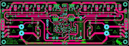
this schematic by ostripper has very deep bass if you ever
get time PLEASE see if it can be modified further if its worthy
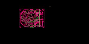
of your appoval i will post gerber pcb was dsigned by Maestro
Alex mm.Working schematic just a quick test.
warm regards
Andrew
Hello jpc2001
greetings and many many thanks for your deep explanation
this schematic by ostripper has very deep bass if you ever
get time PLEASE see if it can be modified further if its worthy
of your appoval i will post gerber pcb was dsigned by Maestro
Alex mm.Working schematic just a quick test.
warm regards
Andrew
Attachments
More 4900Z Mods, Why Not
Improved positive rail ripple eater
After running some tests into a recording interface, the 4900Z turns out to have trouble with PSRR while driving an 8 ohm load -- there's a lot of 120Hz and 240Hz residual, approaching -70dB. Hazy.
One more electrolytic cap on the ripple eater fixes it. Without that cap, the collector of Q16 ripples, and some of that makes it through to the emitter due to Early effect.
With that done, the power-supply harmonics got down to no worse than about -85dB. That's getting close to the residual of the test setup.
Cascode on Q5
In simulation, cascoding Q5 improves PSRR for the B+ rail by ~6dB. Without that cascode, B+ ripple shows up at the collector of Q5 and the input stages have to drive its Cob.
This didn't produce a measurable improvement on the real circuit though.
Grounding Architecture
There's not much wrong with the factory's grounding.
I made one change, moving the center tap of the transformer away from where the speaker grounds return, and closer to the shared terminal of the big filter caps. (Which is how the schematic suggests it should be built, but isn't how this unit was built.)
With that done the grounding architecture becomes:
- There's a noisy ground star that carries charging currents between the filter caps and transformer center tap.
- That hangs off another ground star that carries large signal-like currents from the speaker returns, and zobel returns. This star also connects to the chassis.
- That hangs off a small-signal quiet ground that follows the signal through the power amp and tone controls and volume pot, back to the inputs.
Attachments
- Home
- Amplifiers
- Solid State
- GLA (good little amp) "survivor"