Looks like a very promising project per the simulations.
Can we assume the much larger program power dissipated on the feedback resistor makes the temperature dynamic induced distortion, due to the non-zero tempco of a resistor value, a more serious/practical concern for the CFA than it would in case of a VFA? There are off-the-shelve 50W non-inductive resistors in TO-220 package out there that seem to suit the application. We can probably bolt it onto the main heat sink to greatly reduce its temperature swing by the prograom signal. The best tempco of this type of resistors I've seen is 50ppm/C for the thin film type, and there is a condiserable thermal resistance between the resistor element and its metal case, about 2.5C/W, which means there could still be SOME temperature swing on it at large music dynamic moments. Would that be an issue at all? Perhaps the tempco of the shunt resistor (R9) can become part of the remedy by deliberately selecting on certain tmepco/power rating varieties, and sort of cancelling out what temperature does to the FB resistor?
Just a thought.
Last edited:
...power dissipated on the feedback resistor makes the temperature dynamic induced distortion, due to the non-zero tempco of a resistor value, a more serious/practical concern for the CFA than it would in case of a VFA?
If you want a really low noise VFA then the feedback network ends up pretty low impedance anyway. So I don't see it as a major drawback
There are off-the-shelve 50W non-inductive resistors in TO-220 package...
It has been discussed that if the feedback network is series of identical resistors then all the thermal etc. non linearities cancel out. And it's fairly cheap, thirty or so metal film resistors is still only a few dollars.
I worry that with so many resistors in series the chance of a failure obviously multiplies. No one else seems too concerned.
Reliability can be increased by series-parallel connection but then it ends up a substantial resistor forest.
Best wishes
David
Last edited:
It has been discussed that if the feedback network is series of identical resistors then all the thermal etc. non linearities cancel out. And it's fairly cheap, thirty or so metal film resistors is still only a few dollars.
I worry that with so many resistors in series the chance of a failure obviously multiplies. No one else seems too concerned.
Reliability can be increased by series-parallel connection but then it ends up a substantial resistor forest.
Best wishes
David
Why not all in parallel?
Damir
...
It has been discussed that if the feedback network is series of identical resistors then all the thermal etc. non linearities cancel out. And it's fairly cheap, thirty or so metal film resistors is still only a few dollars.
...
 : resistors in series have increased inductivity ...
BR, Toni
Here is schematic with higher FB resistance.
Damir
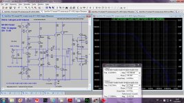
Out of curiosity i simulated this version front end....
Without the 220pf input capacitor the circuit burst in oscillations...
Out of curiosity i simulated this version front end....
Without the 220pf input capacitor the circuit burst in oscillations...
I realy don't know how you simulated that. Here is LTspice simulation front end only, no input cap.
Attachments
I realy don't know how you simulated that. Here is LTspice simulation front end only, no input cap.
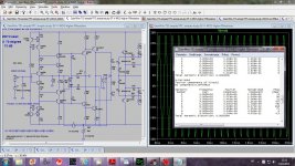
The circuit post2.
Also , there s quite discretanpcies with 94db OLG ,
with 28dB CLG this allow theoricaly 66db distorsion
reduction once the loop is closed but with the claimed
ratios of sub ppm at 1KHz this would require a circuit
that is capable of 0.01% distorsion when open loop ,
quite unexpected and frankly not possible with a two
stages topology as this one , moreover with output levels
being on the 20-30V range and a mosfet output stage that
will inherently produce 0.2 to 0.5% THD with only said 66dB
available loop gain to reduce by , well , 110dB..???
You can freely present here your better circuit, it's open thread for everyone.
I am CFA beginner.
You can freely present here your better circuit, it's open thread for everyone.
I am CFA beginner.
I m afraid you missed the point , wich is not to present
a "better circuit" but to highlight what seems to me as
quite paradoxal.
There s no substancial modifications compared to Manso s
original schematic set apart a lateral mosfet output stage that
is not more linear than his triple EF , yet , distorsion is significantly
lower despite similar loop gain and a worse OS linearity wise ,
hence the OLG linearity requirements are thoses of a closed loop
amplifier if such THD ratios are to be reached when loop is closed ,
wich lead me to question the methodology since no one will negate
that such ratios cant be extracted from a two stages design unless
thoses two stages produces 0.01% THD when open loop and this cant
be the case with two basic serialized common emitters amplifiers ,
be it CFA or whatever other acronym.
Why not all in parallel? Damir
If you use a series potential divider then you can use identical resistors for all the resistors in the feedback network.
So in your amp use a 10 ohm to earth and make the 220 out of 22 of the 10 ohms, from the same batch ideally.
Then all the resistors will have the same temperature coefficient, thermal mass etc.
Even non-linearities from different potentials across the resistors will cancel.
Bruce Hoffer of Audio Precision discussed this non linearity and says it needs attention at the levels you have simulated. I doubt it is audible
... resistors in series have increased inductivity ...
Yes. This was discussed before my time but a few calculations and simulations were done and it seems not to be a problem. You have a bit of a trace from the output back to the input anyway and the resistor inductance should not be too much more than the trace inductance.
I planned to make the feedback resistor from multiple metal films mainly because it is simple and cheap.
Then I found the earlier thread accidentally and read Bruce Hoffer's notes about the same time.
Damir's simulated numbers are so low at 1 kHz he will need to worry about this
. Well done, as usual, by the way. Personally I will probably series-parallel a dozen or so, as many in series as conveniently fit in a direct line from the output back to the input.
Best wishes
David
Last edited:
I m afraid you missed the point , wich is not to present
a "better circuit" but to highlight what seems to me as
quite paradoxal.
There s no substancial modifications compared to Manso s
original schematic set apart a lateral mosfet output stage that
is not more linear than his triple EF , yet , distorsion is significantly
lower despite similar loop gain and a worse OS linearity wise ,
hence the OLG linearity requirements are thoses of a closed loop
amplifier if such THD ratios are to be reached when loop is closed ,
wich lead me to question the methodology since no one will negate
that such ratios cant be extracted from a two stages design unless
thoses two stages produces 0.01% THD when open loop and this cant
be the case with two basic serialized common emitters amplifiers ,
be it CFA or whatever other acronym.
You are forgetting TPOIC used here(or what acronim to give for including OPS in the TPC).
With shunt or Miller + shunt compensation distortion is much higher. With triple BJT OPS I hav't got stable this TPOIC compensation.
Amplifier gain
Dear Damir,
congratulation to your current CFA design.
Would it be possible for you to add some simulations with a little bit more practical gain for a 200W@8R amplifier? E.g.: Gain 30 ~ 680R/22R
Or alternatively: please add your current asc file(s).
Thx, Toni
Dear Damir,
congratulation to your current CFA design.
Would it be possible for you to add some simulations with a little bit more practical gain for a 200W@8R amplifier? E.g.: Gain 30 ~ 680R/22R
Or alternatively: please add your current asc file(s).
Thx, Toni
Dear Damir,
congratulation to your current CFA design.
Would it be possible for you to add some simulations with a little bit more practical gain for a 200W@8R amplifier? E.g.: Gain 30 ~ 680R/22R
Or alternatively: please add your current asc file(s).
Thx, Toni
Here are two versions, 220/10 ohm and 470/22 ohm feedback.
Tell me why 30 is more practical gain?
BR Damir
Attachments
Dave, 22 pieces of 1w metal film is a huge lump of resistors. How could that contribute to the (in)stability margins I don't know. The only experience I have with CFAs is the CFA op-amps for video use at my work years ago. Those were SO-8 SMD devices. In the layouts, we had to cut out the GND plane underneath the inverted input node and all that of its potential, also cutout the plane underneath the output node, and keep all nodes at a minimum possible physical size, in order to avoid peaking and maintain good stability.
MagixBox's idea of a separate riser PCB may work better in terms of physical size. 23 or 24 pieces of 2512 SMD resistors can be populated on both sides of a PCB in a 16x24 mm^2 area, but 14W total dissipation out of that small area is perhaps too much?
MagixBox's idea of a separate riser PCB may work better in terms of physical size. 23 or 24 pieces of 2512 SMD resistors can be populated on both sides of a PCB in a 16x24 mm^2 area, but 14W total dissipation out of that small area is perhaps too much?
Dave, 22 pieces of 1w metal film is a ...lump...
Need a bit of a lump to dissipate 14W, whatever way.
MagixBox's idea of a separate riser PCB may work better in terms of physical size. 23 or 24 pieces of 2512 SMD resistors can be populated on both sides of a PCB in a 16x24 mm^2 area...
The earlier thread discussed a sub-board and addressed your stability concerns with a variety of proposed shields, planes, cut-outs in planes etc.
Interested to read your practical experience after the hypothetical proposals.
Probably no sub-board for me.
I haven't decided yet but it does seem like SMT resistors would fit more neatly.
Best wishes
David
Here are two versions, 220/10 ohm and 470/22 ohm feedback.
Tell me why 30 is more practical gain?
BR Damir
THX!
IMHO higher output power requires higher amplifier gain. Your preamp has little or no extra gain to boost your program material ...
You are forgetting TPOIC used here(or what acronim to give for including OPS in the TPC).
This wont change the fact that there will be at most 66dB loop gain
around the output stage.
That you end with 40db global NFB and 26db local
NFB around the VAS/OS will still be 66dB , unless
you re counting thoses 26dB two fold , for the local
loop and another time for the global loop......
- Home
- Amplifiers
- Solid State
- 200W MOSFET CFA amp