Looks nice! I've been trying to find the current dumping bridge elements and not sure which ones they are (apart from the obvious 1uH and R13 I believe).
Jan
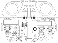
L1, R15, C8 and R6
Regards
Attachments
Last edited:
Hi all,
Here is something to perhaps stir a little interest:
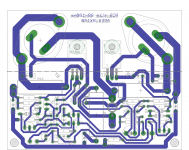
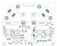
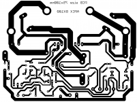
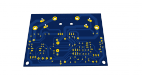
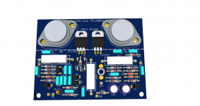
I made a slight change to the board so the TO3s were a little more angled flat and that gained 5mm in width, so the board is now 75x100 instead of 80x100.
Not much gained, but it's something.
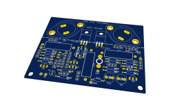
I made some 3D outputs, just for kicks, and even tried adding a corner profile under the TO3s to make it look even a little more bluffing. It's still missing a good size heatsink on its back, but maybe I can add this later.
It's not perfect, and there are always improvements that can be made. It would be nice to test this. The board as it is wouldn't pose any problem to a board house to make, so if we can make it as good and worthy as it can be, maybe we can have a run made.
I have more than 50 2N3773 in my old stock, so those would be better put to work than staying in storage...
Here is something to perhaps stir a little interest:
I made a slight change to the board so the TO3s were a little more angled flat and that gained 5mm in width, so the board is now 75x100 instead of 80x100.
Not much gained, but it's something.
I made some 3D outputs, just for kicks, and even tried adding a corner profile under the TO3s to make it look even a little more bluffing. It's still missing a good size heatsink on its back, but maybe I can add this later.
It's not perfect, and there are always improvements that can be made. It would be nice to test this. The board as it is wouldn't pose any problem to a board house to make, so if we can make it as good and worthy as it can be, maybe we can have a run made.
I have more than 50 2N3773 in my old stock, so those would be better put to work than staying in storage...
Attachments
-
 BX100_bottom_.png42 KB · Views: 494
 -
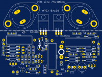 BX100_board_top.png57 KB · Views: 611
 -
 BX100_board_bottom.png52.6 KB · Views: 509
 -
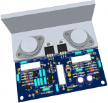 BX100_3.png348.4 KB · Views: 581
 -
 BX100_bottom.png377.8 KB · Views: 411
 -
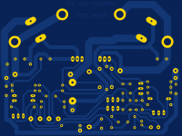
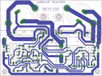 BX100_copper.png55 KB · Views: 606
 -
 BX100_HS.png817.2 KB · Views: 503
 -
 BX100_silk.png668 KB · Views: 512
 -
 BX100_top_silk.png39.7 KB · Views: 682
 -
 BX100_top.png553.2 KB · Views: 3,002
Hi there,
Interesting project
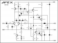
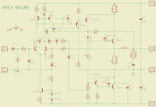
This amplifier uses a bootstrapped VAS(TIS), right?
I don't understand the compensation method, but it's an interesting one.
What the 1.5 pF capacitor is doing in the lower output transistor?
The 150 pF are used to lower the Q and reduce the chances of oscillation, right?
Best regards,
Daniel Almeida
Interesting project
This amplifier uses a bootstrapped VAS(TIS), right?
I don't understand the compensation method, but it's an interesting one.
What the 1.5 pF capacitor is doing in the lower output transistor?
The 150 pF are used to lower the Q and reduce the chances of oscillation, right?
Best regards,
Daniel Almeida
Hi all,
Here is something to perhaps stir a little interest:
I made a slight change to the board so the TO3s were a little more angled flat and that gained 5mm in width, so the board is now 75x100 instead of 80x100.
Not much gained, but it's something.
I made some 3D outputs, just for kicks, and even tried adding a corner profile under the TO3s to make it look even a little more bluffing. It's still missing a good size heatsink on its back, but maybe I can add this later.
It's not perfect, and there are always improvements that can be made. It would be nice to test this. The board as it is wouldn't pose any problem to a board house to make, so if we can make it as good and worthy as it can be, maybe we can have a run made.
I have more than 50 2N3773 in my old stock, so those would be better put to work than staying in storage...
Nice work, thanks for this pcb design.
Regards
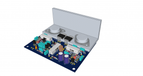
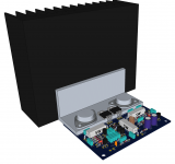
Here is a 3D with a big heatsink added. That heatsink is an SK155 from Fischer, 120mm long.
This brings a topic: calculating the needed heatsink.
I'm thinking of making a spreadsheet with the calculations.
If we use +-55V rails, we're looking at an amp that could give around 150watts rms into 8 ohms, more or less.
Now for the power dissipation, if we start with a gross figure of 75 watts of heat to get rid of. Is that about right?
Attachments
Hi everyone,
Yes, it's a 1.5 nF capacitor (thanks for correcting me Mooly), but I still don't know what that capacitor is doing
And I also don't understand the compensation scheme (it's different from common Miller compensation and TMC/TPC).
Best regards,
Daniel Almeida
It's shunt compensation, QUAD use another inductor but I want only one inductor in amplifier ( 16 turns on 6mm dia with 1mm wire).
Regards
heatsink
I had a Quad 405 II at home for a few days.
I was a bit surprised by the heatsink becoming very hot.
It is the main class A driver which dissipates a lot a heat.
I had a Quad 405 II at home for a few days.
I was a bit surprised by the heatsink becoming very hot.
It is the main class A driver which dissipates a lot a heat.
I never really "got" the current dumping idea tbh. Not the practicalities of it anyway. The Class A part seemed to defeat the object of it all somehow. You had an amp that ran hotter than one with a more optimal AB stage and with worse performance too. I know the original was really for the load the ESL speakers presented yet the majority of 405's were sold for use with conventional drivers.
pic in post10.
The aluminium (or copper) angle transferring heat from the To3s to the sink should be optimised for excellent thermal performance, i.e. coolest To3 Tc.
Make the angle longer than the PCB width. Try 120mm to 150mm long.
Make the angle thick. Try 5mm to 7mm thick.
Keep the To3 as close to the heatsink as possible:
a.) omit the "gap" between the To3 case and the angle. Saw one edge/side of the angle to minimise this gap. Or use an unequal angle (not commonly available)
b.) turn the "angle" upside down, to allow the To3 case to come closer to the sink.
Use Thermal paste between the angle and the sink.
Use many bolts/screws to clamp the angle in very close contact with the sink. Aim for at least 6 clamping points, one up & one down at each side of each To3. Two rows of 5 fixings would be better.
Moly,
I found the Quad 405 sound nice and was a bit surprised it was a bit better than my Self amp. I revised the ground layout of this last one and change its old power supply electrolytics (they dated from before 1994 when I built it) and then prefered it.
Looking at the inside of the Quad, I found that its ground layout could be improved. But as it ws not mine, I did not modify anything.
Many people like the Quad amps. They were not conceived to have the best performances in the world but to avoid any adjustment at the building time in the factory.
I had a Quad 405 II at home for a few days.
I was a bit surprised by the heatsink becoming very hot.
It is the main class A driver which dissipates a lot a heat.
VAS transistor in Quad 405 work with 50mA bias, VAS in BX100 work with 20mA. Class AB amps work with 10mA in VAS and 50mA in output transistors, and this bias must be adjust and thermaly stabilized.
Last edited:
Moly,
I found the Quad 405 sound nice and was a bit surprised it was a bit better than my Self amp. I revised the ground layout of this last one and change its old power supply electrolytics (they dated from before 1994 when I built it) and then prefered it.
Looking at the inside of the Quad, I found that its ground layout could be improved. But as it ws not mine, I did not modify anything.
Many people like the Quad amps. They were not conceived to have the best performances in the world but to avoid any adjustment at the building time in the factory.
I never owned a Quad myself but a friend had the 405 (it would be an early one I think) and the matching preamp running into Gale 401's. Source was vinyl back then. If I'm honest I never really rated the set up, it always sounded dark and lacking any sparkle. Interesting you prefer Dougs amp, that is one I'm familiar with (the Class B blameless).
On the original schematic, it calls for +-45V rails.
Will it be ok without adjusting resistor values anywhere as it is for +-55V ??
For use with an 8 ohm load, we need to look at the outputs SOA.
Amp will work without changes on +/-55V with 8 ohm load.
- Status
- This old topic is closed. If you want to reopen this topic, contact a moderator using the "Report Post" button.
- Home
- Amplifiers
- Solid State
- Current Dumping Amplifier