Here is an LtSpice simulation of the BX100.
THD @20khz on 8ohms load and output power ~105W (before clip):
Fourier components of V(out)
DC component:-0.00724564
Harmonic Frequency Fourier Normalized Phase Normalized
Number [Hz] Component Component [degree] Phase [deg]
1 2.000e+4 4.101e+1 1.000e+0 -9.29° 0.00°
2 4.000e+4 7.162e-3 1.746e-4 65.99° 75.27°
3 6.000e+4 7.558e-3 1.843e-4 -103.29° -94.01°
4 8.000e+4 4.976e-3 1.213e-4 104.06° 113.34°
5 1.000e+5 2.322e-3 5.662e-5 -101.95° -92.67°
6 1.200e+5 2.630e-3 6.413e-5 41.01° 50.30°
7 1.400e+5 4.351e-3 1.061e-4 -141.86° -132.58°
8 1.600e+5 3.570e-3 8.706e-5 52.23° 61.52°
9 1.800e+5 3.029e-3 7.385e-5 -141.99° -132.70°
Total Harmonic Distortion: 0.033287%
For this max power output, it requires 2.63V peak signal input.
@ 1khz the power is up to about 106W and THD not too shabby:
Fourier components of V(out)
DC component:-0.128905
Harmonic Frequency Fourier Normalized Phase Normalized
Number [Hz] Component Component [degree] Phase [deg]
1 1.000e+3 4.118e+1 1.000e+0 -0.22° 0.00°
2 2.000e+3 1.610e-3 3.909e-5 104.23° 104.45°
3 3.000e+3 1.334e-4 3.238e-6 -111.61° -111.39°
4 4.000e+3 3.613e-4 8.772e-6 165.47° 165.69°
5 5.000e+3 2.597e-4 6.305e-6 164.90° 165.12°
6 6.000e+3 1.793e-4 4.354e-6 130.98° 131.20°
7 7.000e+3 1.078e-4 2.618e-6 -158.56° -158.35°
8 8.000e+3 1.572e-4 3.818e-6 165.73° 165.95°
9 9.000e+3 1.025e-4 2.490e-6 172.28° 172.50°
Total Harmonic Distortion: 0.004125%
Also nice @ 20hz, with power still right below 103W:
Fourier components of V(out)
DC component:0.00832485
Harmonic Frequency Fourier Normalized Phase Normalized
Number [Hz] Component Component [degree] Phase [deg]
1 2.000e+1 4.058e+1 1.000e+0 12.17° 0.00°
2 4.000e+1 1.464e-3 3.607e-5 93.89° 81.72°
3 6.000e+1 4.754e-4 1.171e-5 15.40° 3.23°
4 8.000e+1 1.410e-4 3.474e-6 29.00° 16.83°
5 1.000e+2 1.371e-4 3.378e-6 -22.17° -34.34°
6 1.200e+2 4.126e-5 1.017e-6 74.15° 61.98°
7 1.400e+2 1.219e-4 3.003e-6 12.18° 0.01°
8 1.600e+2 6.245e-5 1.539e-6 -6.74° -18.91°
9 1.800e+2 9.011e-5 2.220e-6 0.64° -11.53°
Total Harmonic Distortion: 0.003846%
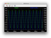
The square wave behavior however probably could use some improvements. There is a somewhat large overshoot on the positive side, but no rining, and perhaps a bit too much slew limiting. I ran the square wave sim with both C2 and C10 shorted.
The THD @20khz is much higher than 1khz and below, so this rise above 1khz may have something to do with the crossover. C2 and C10 don't contribute to any additional thd.
About 117db of open loop gain, not too bad and probably explains mostly why the thd is rather low at lower frequencies. The loop gain may not be enough though to correct enough for the crossover distortion at the higher frequencies.
Closed loop gain is 23.9db.
I haven't tried a tian probe, but the phase margin doesn't seem good and I don't know about the gain margin.
Not bad amp, for ancient parts and topo. Could use a few improvements, but this may be feasible. Raising the phase margin to a safer level and tweak the compensation to make the square wave response better behaved could be nice, and perhaps there is something that could be done to help the crossover at higher frequencies. I see almost no idle current in the upper output, which could explain why the crossover may not happen right at high frequencies...
THD @20khz on 8ohms load and output power ~105W (before clip):
Fourier components of V(out)
DC component:-0.00724564
Harmonic Frequency Fourier Normalized Phase Normalized
Number [Hz] Component Component [degree] Phase [deg]
1 2.000e+4 4.101e+1 1.000e+0 -9.29° 0.00°
2 4.000e+4 7.162e-3 1.746e-4 65.99° 75.27°
3 6.000e+4 7.558e-3 1.843e-4 -103.29° -94.01°
4 8.000e+4 4.976e-3 1.213e-4 104.06° 113.34°
5 1.000e+5 2.322e-3 5.662e-5 -101.95° -92.67°
6 1.200e+5 2.630e-3 6.413e-5 41.01° 50.30°
7 1.400e+5 4.351e-3 1.061e-4 -141.86° -132.58°
8 1.600e+5 3.570e-3 8.706e-5 52.23° 61.52°
9 1.800e+5 3.029e-3 7.385e-5 -141.99° -132.70°
Total Harmonic Distortion: 0.033287%
For this max power output, it requires 2.63V peak signal input.
@ 1khz the power is up to about 106W and THD not too shabby:
Fourier components of V(out)
DC component:-0.128905
Harmonic Frequency Fourier Normalized Phase Normalized
Number [Hz] Component Component [degree] Phase [deg]
1 1.000e+3 4.118e+1 1.000e+0 -0.22° 0.00°
2 2.000e+3 1.610e-3 3.909e-5 104.23° 104.45°
3 3.000e+3 1.334e-4 3.238e-6 -111.61° -111.39°
4 4.000e+3 3.613e-4 8.772e-6 165.47° 165.69°
5 5.000e+3 2.597e-4 6.305e-6 164.90° 165.12°
6 6.000e+3 1.793e-4 4.354e-6 130.98° 131.20°
7 7.000e+3 1.078e-4 2.618e-6 -158.56° -158.35°
8 8.000e+3 1.572e-4 3.818e-6 165.73° 165.95°
9 9.000e+3 1.025e-4 2.490e-6 172.28° 172.50°
Total Harmonic Distortion: 0.004125%
Also nice @ 20hz, with power still right below 103W:
Fourier components of V(out)
DC component:0.00832485
Harmonic Frequency Fourier Normalized Phase Normalized
Number [Hz] Component Component [degree] Phase [deg]
1 2.000e+1 4.058e+1 1.000e+0 12.17° 0.00°
2 4.000e+1 1.464e-3 3.607e-5 93.89° 81.72°
3 6.000e+1 4.754e-4 1.171e-5 15.40° 3.23°
4 8.000e+1 1.410e-4 3.474e-6 29.00° 16.83°
5 1.000e+2 1.371e-4 3.378e-6 -22.17° -34.34°
6 1.200e+2 4.126e-5 1.017e-6 74.15° 61.98°
7 1.400e+2 1.219e-4 3.003e-6 12.18° 0.01°
8 1.600e+2 6.245e-5 1.539e-6 -6.74° -18.91°
9 1.800e+2 9.011e-5 2.220e-6 0.64° -11.53°
Total Harmonic Distortion: 0.003846%
The square wave behavior however probably could use some improvements. There is a somewhat large overshoot on the positive side, but no rining, and perhaps a bit too much slew limiting. I ran the square wave sim with both C2 and C10 shorted.
The THD @20khz is much higher than 1khz and below, so this rise above 1khz may have something to do with the crossover. C2 and C10 don't contribute to any additional thd.
About 117db of open loop gain, not too bad and probably explains mostly why the thd is rather low at lower frequencies. The loop gain may not be enough though to correct enough for the crossover distortion at the higher frequencies.
Closed loop gain is 23.9db.
I haven't tried a tian probe, but the phase margin doesn't seem good and I don't know about the gain margin.
Not bad amp, for ancient parts and topo. Could use a few improvements, but this may be feasible. Raising the phase margin to a safer level and tweak the compensation to make the square wave response better behaved could be nice, and perhaps there is something that could be done to help the crossover at higher frequencies. I see almost no idle current in the upper output, which could explain why the crossover may not happen right at high frequencies...
Attachments
Here is an LtSpice simulation of the BX100.
THD @20khz on 8ohms load and output power ~105W (before clip):
Fourier components of V(out)
DC component:-0.00724564
Harmonic Frequency Fourier Normalized Phase Normalized
Number [Hz] Component Component [degree] Phase [deg]
1 2.000e+4 4.101e+1 1.000e+0 -9.29° 0.00°
2 4.000e+4 7.162e-3 1.746e-4 65.99° 75.27°
3 6.000e+4 7.558e-3 1.843e-4 -103.29° -94.01°
4 8.000e+4 4.976e-3 1.213e-4 104.06° 113.34°
5 1.000e+5 2.322e-3 5.662e-5 -101.95° -92.67°
6 1.200e+5 2.630e-3 6.413e-5 41.01° 50.30°
7 1.400e+5 4.351e-3 1.061e-4 -141.86° -132.58°
8 1.600e+5 3.570e-3 8.706e-5 52.23° 61.52°
9 1.800e+5 3.029e-3 7.385e-5 -141.99° -132.70°
Total Harmonic Distortion: 0.033287%
For this max power output, it requires 2.63V peak signal input.
@ 1khz the power is up to about 106W and THD not too shabby:
Fourier components of V(out)
DC component:-0.128905
Harmonic Frequency Fourier Normalized Phase Normalized
Number [Hz] Component Component [degree] Phase [deg]
1 1.000e+3 4.118e+1 1.000e+0 -0.22° 0.00°
2 2.000e+3 1.610e-3 3.909e-5 104.23° 104.45°
3 3.000e+3 1.334e-4 3.238e-6 -111.61° -111.39°
4 4.000e+3 3.613e-4 8.772e-6 165.47° 165.69°
5 5.000e+3 2.597e-4 6.305e-6 164.90° 165.12°
6 6.000e+3 1.793e-4 4.354e-6 130.98° 131.20°
7 7.000e+3 1.078e-4 2.618e-6 -158.56° -158.35°
8 8.000e+3 1.572e-4 3.818e-6 165.73° 165.95°
9 9.000e+3 1.025e-4 2.490e-6 172.28° 172.50°
Total Harmonic Distortion: 0.004125%
Also nice @ 20hz, with power still right below 103W:
Fourier components of V(out)
DC component:0.00832485
Harmonic Frequency Fourier Normalized Phase Normalized
Number [Hz] Component Component [degree] Phase [deg]
1 2.000e+1 4.058e+1 1.000e+0 12.17° 0.00°
2 4.000e+1 1.464e-3 3.607e-5 93.89° 81.72°
3 6.000e+1 4.754e-4 1.171e-5 15.40° 3.23°
4 8.000e+1 1.410e-4 3.474e-6 29.00° 16.83°
5 1.000e+2 1.371e-4 3.378e-6 -22.17° -34.34°
6 1.200e+2 4.126e-5 1.017e-6 74.15° 61.98°
7 1.400e+2 1.219e-4 3.003e-6 12.18° 0.01°
8 1.600e+2 6.245e-5 1.539e-6 -6.74° -18.91°
9 1.800e+2 9.011e-5 2.220e-6 0.64° -11.53°
Total Harmonic Distortion: 0.003846%
The square wave behavior however probably could use some improvements. There is a somewhat large overshoot on the positive side, but no rining, and perhaps a bit too much slew limiting. I ran the square wave sim with both C2 and C10 shorted.
The THD @20khz is much higher than 1khz and below, so this rise above 1khz may have something to do with the crossover. C2 and C10 don't contribute to any additional thd.
About 117db of open loop gain, not too bad and probably explains mostly why the thd is rather low at lower frequencies. The loop gain may not be enough though to correct enough for the crossover distortion at the higher frequencies.
Closed loop gain is 23.9db.
I haven't tried a tian probe, but the phase margin doesn't seem good and I don't know about the gain margin.
Not bad amp, for ancient parts and topo. Could use a few improvements, but this may be feasible. Raising the phase margin to a safer level and tweak the compensation to make the square wave response better behaved could be nice, and perhaps there is something that could be done to help the crossover at higher frequencies. I see almost no idle current in the upper output, which could explain why the crossover may not happen right at high frequencies...
Nice work and not bad for class B amp
Regards
Not bad at all. The thd @ 20k is a little high and the phase margin probably could be improved some.
With a little tweaking and better stability it can work nicely.
Being based on the 2N3773, it's like doing a 2N3055 on steroid.
If we can tweak this without too many changes in the topo, the pcb design won't need much adjustment. Makes a good diy project, and many of us with old stock 2N3773 can put them to good use.
btw: the older bgw amps were almost all using that 2N3773 tranny, and a lot of people thought it really sounded great, plus those are rugged.
What is the distortion of a ClassB amplifier when outputting typical powers of -10dB and -20dB ref maximum power?
Might be worth checking at -30dB as well !
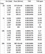
To make things simple and avoid calculations with logs every time, I ran the sims for input signals to obtain about 2/3 (~70W), 1/2 (~50W), 1/4 (~25W) and ~1W, as well as full power before clipping, which is near 105W, and only on 8ohms load, as 4ohms wouldn't be recommended with only one pair of outputs.
I ran everything for 20hz, 1k, 10k and 20k, keeping the input level the same at each frequency, so we can see the effect of roll off at the extremities of the spectrum.
So here are some THD readings, starting with the full power:
Vin = 2.63Vpk
0.033287% @ 20k / 105.11W
0.008832% @ 10k / 105.78W
0.004125% @ 1k / 106.01W
0.003846% @ 20 / 102.95W
Vin = 2.137Vpk
0.012466% @ 20k / 69.395W
0.007410% @ 10k / 69.844W
0.003653% @ 1k / 69.99W
0.003294% @ 20 / 67.973W
Vin = 1.807Vpk
0.015052% @ 20k / 49.618W
0.006387% @ 10k / 49.939W
0.003541% @ 1k / 50.043W
0.003134% @ 20 / 48.601W
Vin = 1.278Vpk
0.030720% @ 20k / 24.819W
0.004108% @ 10k / 24.979W
0.003436% @ 1k / 25.032W
0.002984% @ 20 / 24.31W
Vin = 0.256Vpk
0.008355% @ 20k / 995.87mW
0.003766% @ 10k / 1.0023W
0.003410% @ 1k / 1.0044W
0.002834% @ 20 / 975.45mW
I think it's quite decent for a class B. Only the high end above 10k is a little higher on thd. The lower power should make the crossover distortion more obvious, but this doesn't seem to be the case. The thd does rise a little with increasing power, but not so much, except that it rises a lot more at the high end of the spectrum.
Logically using 2 pairs would provide lower distortion, while allowing more practical use of 4ohms loads. But in any case, a beefy heatsink remains a plus.
I've been trying a few things and made some tweaks on this one. I wasn't able to get rid of the overshoot on the square wave, but I was able to get nearly 40 degrees of phase margin (using a tian probe on the main feedback loop), managed to remove a couple of compensation caps and lower a few values. Plus I changed the drivers' emitter connections from the 0.1ohms resistors to the rail and output bus, which decreased the distortion nicely, increased open loop gain some from about 117db to about 125db, which probably is the main cause of the lower distortion. This also allows adding one more diode in series with D5, which would receive a resistor in parallel and also a trimmer also in parallel, to allow giving some idle current and go more into a class AB mode. This also nicely reduces distortion and I was able to cut the thd @ 20k down to about 1/3rd of before (about 111ppm now).
I haven't yet looked at all frequencies and power level, but this might get interesting. The lower compensation cap values and removal of a couple of them does decrease the thd quite a bit, and the compromises made still allows keeping a somewhat decent phase margin.
I haven't seen any oscillation issues, but this would have to be verified with a complex reactive load.
So here it is!
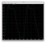
After trying many tweaks and values. Although the changes don't go very far, the improvement in phase margin and distortion are nice. However the square wave behavior hasn't really improved, the overshoot is still there, although there is no ringing. The square wave behavior is very asymmetrical, with a different slew rate for up and down, and there seems to be some lag before the signal starts going down. The presence of C10 really does a number on that square wave, it doesn't even look as such. But I ran the tests with C2 and C10 shorted, to keep it somewhat square...
I upped C10's value a bunch, as this really makes a huge difference at the low end. It's a little tricky to find high quality non polar audio caps in large values, but it's worth the efforts, as the difference is undeniable. And a good film cap can be added in parallel with it. Such high value caps are found in the bryston amps, as they use up to 2200u in many amps. That can't be a random choice. I limited C10's value to 470u, but the bigger the better.
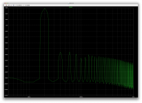
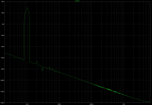
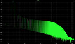
The thd data collected in the table shows how the improvements have been throughout the whole bandwidth. I left both C2 and C10 (& C16) active to ran all the measurements. I added a couple of screenshots of the FFT plots for 1k and 20k.
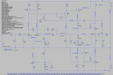
The schematic shows the extra D6 in series with D5, and the 2 resistors in parallel are there to adjust the bias to a class AB level (~65mA). The R19 of 27ohms would be fixed and the R20 would be a 100ohms trimmer. I chose those values carefully as to prevent any mishaps when adjusting the bias, to keep it in a range that is safe enough, in case something happens with the cursor in R20, the bias would not shoot up too far up and cause something to blow. I know this makes an adjustment that wasn't there before, and it does change the class B amp into a class AB, but that does make a big difference, which we can see in the results. Obviously it's more linear and the crossover distortion must have gone down.
A few parts fewer here and there, and a few new ones, but nothing really major.
Please scrutinize this, and if there is any interest, since the pcb was already designed, those changes can easily be made for a newer version.
After trying many tweaks and values. Although the changes don't go very far, the improvement in phase margin and distortion are nice. However the square wave behavior hasn't really improved, the overshoot is still there, although there is no ringing. The square wave behavior is very asymmetrical, with a different slew rate for up and down, and there seems to be some lag before the signal starts going down. The presence of C10 really does a number on that square wave, it doesn't even look as such. But I ran the tests with C2 and C10 shorted, to keep it somewhat square...
I upped C10's value a bunch, as this really makes a huge difference at the low end. It's a little tricky to find high quality non polar audio caps in large values, but it's worth the efforts, as the difference is undeniable. And a good film cap can be added in parallel with it. Such high value caps are found in the bryston amps, as they use up to 2200u in many amps. That can't be a random choice. I limited C10's value to 470u, but the bigger the better.
The thd data collected in the table shows how the improvements have been throughout the whole bandwidth. I left both C2 and C10 (& C16) active to ran all the measurements. I added a couple of screenshots of the FFT plots for 1k and 20k.
The schematic shows the extra D6 in series with D5, and the 2 resistors in parallel are there to adjust the bias to a class AB level (~65mA). The R19 of 27ohms would be fixed and the R20 would be a 100ohms trimmer. I chose those values carefully as to prevent any mishaps when adjusting the bias, to keep it in a range that is safe enough, in case something happens with the cursor in R20, the bias would not shoot up too far up and cause something to blow. I know this makes an adjustment that wasn't there before, and it does change the class B amp into a class AB, but that does make a big difference, which we can see in the results. Obviously it's more linear and the crossover distortion must have gone down.
A few parts fewer here and there, and a few new ones, but nothing really major.
Please scrutinize this, and if there is any interest, since the pcb was already designed, those changes can easily be made for a newer version.
Attachments
btw: I realize that having added a bias current to this topo now makes it a class AB and it's no longer B, but I suppose the "current dumping" label could still be applied. The topo hasn't really changed. Those few tweaks have brought the thd down a bunch, although it hasn't helped the square wave behavior, the slew rate seems still as it was and fairly decent. Anything done to reduce thd should also reduce other distortions, such as tim and the likes. The plain current dumping idea may sound ok but if it doesn't fully eliminate the crossover distortion as it's supposed to, then why should it stay that way when we can improve uppon it? 
The distortion figures also confirm you have not simulated a ClassB amplifier.
With the changes made to lower it, and now having an idle current, of course it no longer qualifies as class b. But without doing that, the thd is higher and I found no other ways to lower it.
This concept of current dumping with a class b output stage is supposed to dispense using idle current, avoid adjusting bias, and get low distortion, but what we find is that it comes a little short on that, so if we want to improve it, the concept must be altered a little.
The result is better, unless I left something out. Can anyone further scrutinize this? I think it's worth building.
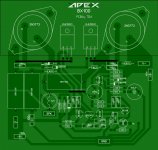
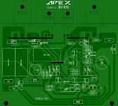
Hello apexaudio. It is a beauty.BX100
Here is an LtSpice simulation of the BX100.
thank you for this file.
you can see that the amp oscillates lightly during 0 crossing
thank you for this file.
you can see that the amp oscillates lightly during 0 crossing
Yes, it does a little, at the crossover, which isn't quite at the real zero point, with the phase shift. It's a short lived and small amplitude, and it's likely what makes up the bulk of that distortion.
If we could prevent this, then it's likely the distortion figure would drop drastically. With no idle current at all, that crossover distortion is much much greater.
it might sound well if not this artefact
It likely sounds fairly nice in its original form, but yes, it is likely to sound even better without those artefacts.
I've tried various tweaks in simulations and have seen the distortion drop quite a bit already from the plain current dumping original design. Obviously the tweaks would likely disqualify it as current dumping, but hey, this is something that brings quality up, so it's up to the builder to make a choice.
If anyone has ideas on how to rid us of those small artefacts, that is without causing more issues elsewhere, that would be nice to share.
None can expect stellar performance from a plain class B amp. Bringing it more into class AB does improve it. Remains to be seen if it can be improved further.
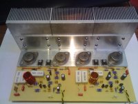
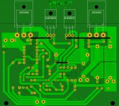
Transistors are on the bottom side.
Attachments
Last edited:
- Status
- This old topic is closed. If you want to reopen this topic, contact a moderator using the "Report Post" button.
- Home
- Amplifiers
- Solid State
- Current Dumping Amplifier