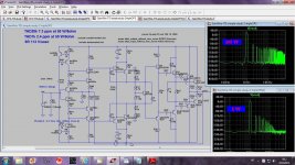
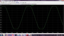
This is my best(up to now) CFA, with very benign hormonic distribution even at 20Khz.
THD20k is 7.74 ppm at 52W on 8 ohm load. Nex step, simplification.
BR Damir
This looks like a good candidate to discuss for CMA-Phase One.
Thx-RNMarsh
This looks like a good candidate to discuss for CMA-Phase One.
Got a candidate to show that is similar to discuss? Git it out and put it up or what would be changed with this circuit?
-THxRNMarsh
Thx-RNMarsh
Last edited:
This is my best(up to now) CFA, with very benign hormonic distribution even at 20Khz.
THD20k is 7.74 ppm at 52W on 8 ohm load. Nex step, simplification.
BR Damir
Very nice dadod!
I tried to add a quick and (very) dirty 4 transistor error correction to the output stage of the VSSA to see what's happens.
Not so good than Dadod: 4ppm at 1Khz and 11ppm at 20K, but, look at the bandwidth and imagine the slew rate:
(Input and VAS unchanged).
Not so good than Dadod: 4ppm at 1Khz and 11ppm at 20K, but, look at the bandwidth and imagine the slew rate:
(Input and VAS unchanged).
Attachments
I would opt for the slew rate -- as we want to know what difference it makes... a few ppm one way or the other isnt as differentiating of designs -- maximize the differences.
Can you make it better than the very dirty circuit you used?
Have you read Samuel Groner's comments on D.Selfs book (comment dated Feb 24 2011)... specifically his Fig 59 triple emitter follower ops on his page 51..... [its a long comment ! ]
THx-RNMarsh
Can you make it better than the very dirty circuit you used?
Have you read Samuel Groner's comments on D.Selfs book (comment dated Feb 24 2011)... specifically his Fig 59 triple emitter follower ops on his page 51..... [its a long comment ! ]
THx-RNMarsh
Last edited:


I tried to add a quick and (very) dirty 4 transistor error correction to the output stage of the VSSA to see what's happens.
Not so good than Dadod: 4ppm at 1Khz and 11ppm at 20K, but, look at the bandwidth and imagine the slew rate:
(Input and VAS unchanged).
Hi Esperado,
From the Close Loop Gain it is not possible to imagine the slew rate, it is not directly correlated.
BR Damir
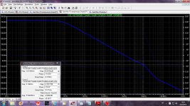
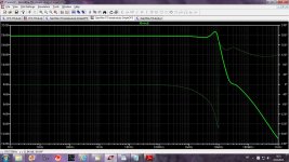
Yes, of course. What i mean was slew rate can be better, can't be worseFrom the Close Loop Gain it is not possible to imagine the slew rate, it is not directly correlated.
")
~545v/µs for 90% of +-28.5V out.
Dunno.. if i get some time to dig. As Dadod will probably confirm, all this is quite acrobatic to keep-it stable. For the moment, my error-correction circuit is not symmetrical, Q problem at 30MHz and i don't want a complicated circuit.Can you make it better than the very dirty circuit you used?
Personally, i'm not so much interested by harmonic distortion numbers, so, it was purely educational (my own education ;-). Just to feel what we can expect from this side.
Shame on me, but i don't read too much about electronic. And will never buy a book from Mister Self ;-).Have you read Samuel Groner's comments on D.Selfs book
Last edited:
Shame on me, but i don't read too much about electronic. And will never buy a book from Mister Self ;-).
I'll take that as a no. But, the all mighty, the great and powerful OZ (Internet) knows. Ask and you will find an answere (usually): Via the great OZ of the Internet - maybe find out in sim if this or one of similar variation would be better if adapted here. Especially at 50W or greater levels.

Thx-RNMarsh
Last edited:
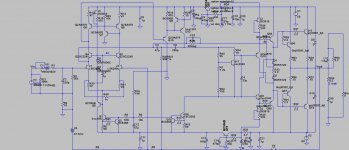
I simulated, some years ago, VFA amp using Groner suggested triple OPS. It simulated quite good, THD20k less the 1ppm at 70W/8ohm. With normal triple I've got similar result(it is my working TT amp) and thermal stabilizasion with Groner triple was a bit tricky, Vbe multiplier should work on only 1.4V and in simulation I could not get it stable enough.
Here is schematic.
BR Damir
Here is schematic.
BR Damir
Attachments
I'll take that as a no. But, the all mighty, the great and powerful OZ (Internet) knows. Ask and you will find an answere (usually): Via the great OZ of the Internet - maybe find out in sim if this or one of similar variation would be better if adapted here. Especially at 50W or greater levels.
Thx-RNMarsh
BTW, the whole paper is a good read (as is everything else Samuel Groner
has on his website):
http://www.sg-acoustics.ch/analogue_audio/power_amplifiers/pdf/audio_power_amp_design_comments.pdf
I simulated, some years ago, VFA amp using Groner suggested triple OPS. It simulated quite good, THD20k less the 1ppm at 70W/8ohm. With normal triple I've got similar result(it is my working TT amp) and thermal stabilizasion with Groner triple was a bit tricky, Vbe multiplier should work on only 1.4V and in simulation I could not get it stable enough.
Here is schematic.
BR Damir
That makes sense to me re thermal stability. lets see if we can make the full power output distortion lower and slew rate higher - all else being same.
Thx-RNMarsh
Andrew, if this is the qx-Amp you posted in #1045, it is indeed an excellent amp.I have shown a CFA sim design earlier that gets to the 5 ppm level at 20 kHz at full power and drops off rapidly after that. The OPS is indeed the limiting factor, but I don't think additional complexity to lower it further is warranted.
But I think it's cheating to quote THD with your supa AFEC connected.
There is no need for such tricks as the basic amp is very good indeed. That's not to say it can't be improved and simplified further.
Converting the Diamond input to simple CFA drops THD and gets rid of 2 devices. The improvement isn't quite 3dB which implies we are getting near the point where Diamond will show advantage but we are still some way from that.
I don't see why we are worried about the giarnomous caps.Lets organise a group buy for Mr Marsh to produce 6800uF caps with oil squeezed from Taipans by Virgins and cased in hand carved Unobtainium.
My experiments have been very encouraging. Cooktown has large supplies of Taipans but I'm fresh out of Virgins
______________
So if we are voting, I'll vote for qx-Amp and its simpler derivatives especially with 'simple CFA input'.
______________
On that basis, many of the circuits proposed should be disqualified. There are all (with notable exceptions) exceedingly complex and have WORSE performance in all respects than much simpler circuits.RNMarsh said:Even if they produce zero distortion themselves... they do not reduce the circuits distortion. They have to go for that reason alone.
There seems to be a tendency for this august forum to prefer extremely complex solutions even (especially?) if they perform WORSE than much simpler and standard solutions
Last edited:
- Home
- Amplifiers
- Solid State
- CFA Topology Audio Amplifiers