Hi Bob,hi Whaleman
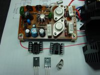
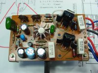
i was wondering about what looks like a homemade stripboard with 2 recifiers and 2 capacitors? ajacent to the bottom of the transformer?
That Radio Shack board replaced the bank of 8 diodes. I added the 100 uF for extra filtering. It has a small ceramic cap across the AC side as well.
Today, after a few attempts, I got the right channel done and Wow! I am blown away by the outcome! It is so good it is holographic. It has uncovered another layer of material from the music and bass and treble extend way beyond where they used to. It is light years from whatever was stock in sound and has totally transformed this humble receiver. Here are some pics. I am going to have to look into this second harmonic distortion stuff that Mooly refers to because I hear something out of the Sansui that I am not used to hearing from these vintage units--and other for that matter--and it is quite pleasing and fills a void that is present in flat and two-dimensional systems.
Attachments
the noise was probably produced by the new relocation of the rectifier ..Machines with that rate of complication but most important with the specific grounding scheme that is ""all ground all around "" have by far more sensitivity to wiring /distance / loop issues that the Japanese worked out before put the machine in the market .
---What i am trying to say is that a slight disturbance of the ground topology / balance will produce some problem sooner or later ...
---that type/style of bypassing will not help the amp ...many people misunderstand bypass and decoupling which is totally two different things .
---Mixing up semis especially in the output section is a very bad practice and will eventually end up to some kind of fail or bad performance
---Using Sylvania outputs is even worst practice
---To be sure of what you 've done you need to scope the amp and make extensive tests . often circuits behind the drivers for this style of amplifiers and geriatric semis DO NOT have the ability to drive properly modern TO220 semis ...
What is confusing me very much is that looking schematics of 5000A and 5000x seems to be that both of the drivers are NPN am I missing something here ?
what saves your a** at this point is that amplifier is capacitor coupled and if something goes wrong there is no chance that will come out on the speaker ...
Looking at your rather dirty trimmers located in the exact same position with the opposite channel reminds me of ""kids practice "" when the dont know how to set up the amplifier properly set trimmers in about middle position and if the amplifier sounds work alike in the other channel ...
Even though i repair >400 amplifiers per year when ever i see trimmers ""set up "" alike its a sign of a very bad practice and most of the time settings are wrong ...especially for amplifiers that use no precision or accurate parts when it comes mostly ton resistors trimmers and capacitors .
There is absolutely no chance that trimmers have equal settings in both of the amplifiers ....
the transistors originally exist on the amplifier have a ft of 20 MHZ what makes you think that a 200MHZ transistor is a drop in replacement ????....200MHZ transistor might work and even sound better but NOT as a drop in replacement it will probably require some extra compensation
To my understanding VAS scheme will not be able to drive these transistors ...
I think you are doing things very wrong i think you need check the machine properly!!!
listening to it will not tell you enough
Kind regards
Sakis
Hi Sakis,
Appreciate your comments, I will digest them carefully.
BUT, yesterday I sat before a $300,000 Tidal system and few others costing less. Later I was before the Sansui.
My ears contradict what you say about the Sansui and if it ends up blowing up again, I am just back to where I started minus $15 or so.
The "child's play" trim pots were measured and so were voltages at these new transistors to ensure they matched side to side and per the Toshiba spec sheets, so it was not done in a haphazard way.
I assume from your assertion that you already tried this with disastrous results...maybe that awaits me, but for now I am enjoying quite a bit
Thanks again for taking time to give your opinion and thoughts.
Can i be more mean now ?
Edit time is gone and i have to correct my self taking now as a fact that you don't have a scope or the ability to measure the amplifier cause if you did you will never use CAT5 cables in the things you make ...
Often things are said in a pretty rough way but the intention is very polite trust me on that ...we all like amplifiers to rock and users to be happy Most of us like to help and solve the problems not bypass them !!
Kind regards
Sakis, that doesn't CAT 5 for line level cable ... i like dark and dead quite preamps free from crosstalk between sources and channels !!!
Last edited:
Can i be more mean now ?
Edit time is gone and i have to correct my self taking now as a fact that you don't have a scope or the ability to measure the amplifier cause if you did you will never use CAT5 cables in the things you make ...
Often things are said in a pretty rough way but the intention is very polite trust me on that ...we all like amplifiers to rock and users to be happy Most of us like to help and solve the problems not bypass them !!
Kind regards
Sakis, that doesn't CAT 5 for line level cable ... i like dark and dead quite preamps free from crosstalk between sources and channels !!!
No problem, we all hold our opinions dear but let them loose sometimes. SO, here I go.
I have two very competent scopes, one tube and one solid state. I admit they sit mainly unused since most of the time I am tuning stuff and not necessarily fixing, so my ears are my final toolset.
I love using CAT6 for line level and use the plenum-rated twisted pair anit x-talk Teflon insulation type. Love it and the way it sounds and the insulation is never affected by mistakes with the solder iron. And so do many other DIYers. Some even use it for speakers cables and I have some of those laying around.
The Sansui has not blown up yet
Last edited:
Good to know your Sansui 5000A is working fine. and about wires... I use microphone triple shielded wires for the inputs and for the rest I use regular jumper wires like. for power supply I use a little heavier wires.I ALWAYS try to "separate" the AC and the DC voltages away from each other and SPECIALLY any AC voltages away from inputs. I have seen people using speaker wires in heavy power supply's it works, but I do not support that.
it works, but I do not support that.Sakis, some comments on your advise (and appreciated your input and observations BTW):
the noise was probably produced by the new relocation of the rectifier ..Machines with that rate of complication but most important with the specific grounding scheme that is ""all ground all around "" have by far more sensitivity to wiring /distance / loop issues that the Japanese worked out before put the machine in the market .
The rectifiers were replaced in the same location as the old ones using the same ground wires.
---What i am trying to say is that a slight disturbance of the ground topology / balance will produce some problem sooner or later ...
I doubt there was any topology since the Sansui had signal, AC, and DC wires tightly bound together and was probably the source of the "stray hum pickup". Once I separated these wires and ran them apart from each other, the hum is inaudible.
---that type/style of bypassing will not help the amp ...many people misunderstand bypass and decoupling which is totally two different things .
It is my understanding that this has been standard practice in high-end audio. These caps are direct signal carriers and their quality affects the output quality. The bypasses are somewhat symmetrical .1/2.2/10/100 uF. I have a Meitner amp with a bunch of 2.2 uF film bypass caps in similar fashion. Call me a copy cat, but if I hear it I believe in the practice
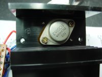
---Mixing up semis especially in the output section is a very bad practice and will eventually end up to some kind of fail or bad performance
---Using Sylvania outputs is even worst practice
This is all I had in hand, probably from another Sansui or Marantz of similar vintage. So far so good, not sure why the Sylvanias could be so bad
---To be sure of what you 've done you need to scope the amp and make extensive tests . often circuits behind the drivers for this style of amplifiers and geriatric semis DO NOT have the ability to drive properly modern TO220 semis ...
I failed to mention that I did replace the input transistors to Fairchild Semiconductors...if I have spare time in the future, I may scope to see what I am hearing.
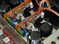
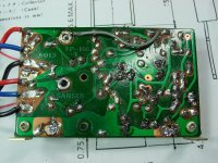
What is confusing me very much is that looking schematics of 5000A and 5000x seems to be that both of the drivers are NPN am I missing something here ?
These are PNP/NPN complimentary pairs before and after (see pics).
what saves your a** at this point is that amplifier is capacitor coupled and if something goes wrong there is no chance that will come out on the speaker ...
The capacitors have been doing nothing to protect my speakers, the fuses did and I saw it in action. These capacitors actually store energy and released it upon my unsuspecting speakers as a big pop or even a spark as I was hooking them up, even with the unit off. If you keep the speakers connected, then the load drains the capacitors as you turn the unit off. But if you turn the unit on without the speakers connected, you have a surprise waiting for you when you go to connect your speakers
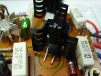
Looking at your rather dirty trimmers located in the exact same position with the opposite channel reminds me of ""kids practice "" when the dont know how to set up the amplifier properly set trimmers in about middle position and if the amplifier sounds work alike in the other channel ...
These trimpots are probably silver plated, so that is why they look dirty. I hear silver oxide is conductive?... and starting things off in the middle might be more for safety sake than anything else. They are not in the middle and were never there that I am aware of.
There is absolutely no chance that trimmers have equal settings in both of the amplifiers ....]
The multimeter was used to bring both sides to the same/equal voltages.
the transistors originally exist on the amplifier have a ft of 20 MHZ what makes you think that a 200MHZ transistor is a drop in replacement ????....200MHZ transistor might work and even sound better but NOT as a drop in replacement it will probably require some extra compensation
100 MHz vs. 200 MHz is close enough, no?
Hope this sheds some light on the subject, not trying to start an argument.
Thanks.
Sakis
Last edited:
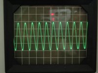
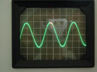
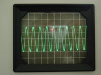
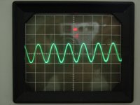
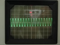
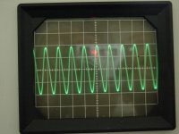
This afternoon, I ran some test tones through the Sansui and read them on the oscilloscope. The pictures below represent the right channel pics 1,2,3: 500, 1250, and 8000 Hz tones. Pictures 4, 5, and 6 are the left channel, same frequencies.
The difference in the waves is due to changes in the settings of the scope. The grid on the scope is crooked as well, or the tube inside.
The difference in the waves is due to changes in the settings of the scope. The grid on the scope is crooked as well, or the tube inside.
Attachments
Last edited:
Long term performance of transistor upgrade
Hi Whaleman -
I read through your thread as I'm starting a restoration on the Sansui 5000 that has already had the F-6013 board replacement. You received dire warnings that your part substitution was wildly out of spec and risked destroying your system. So, three years later how is your unit performing? Would you recommend any changes to your rebuild?
Thanks
Uh ! Me ? Sleeping...
I thought that it was a first msg starting the thread
NOW I see .... The SANSUI 5000A
Good job ! Why 1 mF instead of 2m2 at Cout ???
I thought that it was a first msg starting the thread
NOW I see .... The SANSUI 5000A
Good job ! Why 1 mF instead of 2m2 at Cout ???
Hi Whaleman -
I read through your thread as I'm starting a restoration on the Sansui 5000 that has already had the F-6013 board replacement. You received dire warnings that your part substitution was wildly out of spec and risked destroying your system. So, three years later how is your unit performing? Would you recommend any changes to your rebuild?
Thanks
Update. After a few years playing beautifully, I sold them. Heard back front the buyer on the other coast, he liked it a lot and sent pics.
The other buyer being local would assume would be back with any problems and was quite pleased with its sound. It has been a couple years now.
- Status
- This old topic is closed. If you want to reopen this topic, contact a moderator using the "Report Post" button.
- Home
- Amplifiers
- Solid State
- Sansui 5000A Hum Help...