Get a couple (or more) of 1% 1r0 and use them to "define" the current passing. This is REF = reference resistor.It is very difficult to get an accurate measurement of such low value resistors.
Place some DUT resistors in series and feed them from the 1r0||1r0 resistor pair. DUT = Device Under Test.
Pass ~100mAdc through the long string of resistors.
Measure the voltage across the 1% 0r5 to find the TEST current. Pq for REF is 5mW (2.5mW each)
Measure the voltage across each DUT.
Now you can calculate the DUT resistance to <2% error. Mark each DUT with new value.
You can use this METHOD with a more accurate REF and get to within +-0.1% for <1r resistors, (if the DMM voltage across REF ~= to the DUT voltage then DMM errors are almost eliminated, i.e. use three 1r0 0.5% to get your results to +-0.7%).
Last edited:
Thanks , a lot ,also I suggest you to mount Q3 under PCB in contact with heatsink ......")
Regards,Alex
That sounds difficult to do. I might try changing it to a TO-225 and mounting it on top of one of the outputs.
Get a couple (or more) of 1% 1r0 and use them to "define" the current passing. This is REF = reference resistor.
Place some DUT resistors in series and feed them from the 1r0||1r0 resistor pair. DUT = Device Under Test.
Pass ~100mAdc through the long string of resistors.
Measure the voltage across the 1% 0r5 to find the TEST current. Pq for REF is 5mW (2.5mW each)
Measure the voltage across each DUT.
Now you can calculate the DUT resistance to <2% error. Mark each DUT with new value.
You can use this METHOD with a more accurate REF and get to within +-0.1% for <1r resistors, (if the DMM voltage across REF ~= to the DUT voltage then DMM errors are almost eliminated, i.e. use three 1r0 0.5% to get your results to +-0.7%).
Can you draw up a little schematic for that? I'm having trouble forming a picture.
Thanks, Terry
You don't set the 100mAdc.
Measure the voltage across the 1% 0r5 to find the TEST current.
You don't set the 100mAdc.
You said "Pass ~100mAdc through the long string of resistors."
That was confusing.
I never use a To126 for Vbe multiplier.
To92 or sot23
On what amps did you do this and how did you attach them to the heatsink or outputs so they could help control thermal runaway?
To92 in a tight fitting pocket next to the output device, I think Leach showed this. Quasi showed it.
sot23 glued to the Collector/Drain(Vertical) lead "dead bug" style and as close to the pakage to get quickest heat up/response.
I use them for tempco correction, not for thermal runaway.
sot23 glued to the Collector/Drain(Vertical) lead "dead bug" style and as close to the pakage to get quickest heat up/response.
I use them for tempco correction, not for thermal runaway.
~ = approximately
You still don't explain how you set that, even if it is approximate.
To92 in a tight fitting pocket next to the output device, I think Leach showed this. Quasi showed it.
sot23 glued to the Collector/Drain(Vertical) lead "dead bug" style and as close to the pakage to get quickest heat up/response.
You didn't say what amps you use either of these methods on, just that you always use them.
I use them for tempco correction, not for thermal runaway.
Yes, that is what I meant and what I believe Alex was referring to.
Almost every amp I have built uses BD139 or equivalent for the VBE. I have some awesome sounding and behaving amps.
Guys, please note that the bias controller does NOT WORK like a normal class AB bias controller.
The sx-Amp bias controller measures the voltage drop across the two emitter resistors PLUS the Vbe drop across the PNP output device. The PNP output device Vbe is cancelled by the bias controller Vbe - i.e. 1st order correction.
You may get better control of the output stage current by thermally coupling it to the OPS heatsink - but it is not critical and in a class A amp you do not have to contend with the short term bias shifts due to temperature that you get in class AB. On my sx-Amp build, I get 40mA of bias current shift on a total of 1.4A OPS standing current - this is very good. In this design, even if the bias shifted by a couple of hundred mA, I doubt it would cause any major issues. There are no therma runaway issues in this design - it cannot happen because we measure the current directly across the OPS emitter degen resistors and control the OPS bias from that. Class AB typically adjusts the OPS bias based on temperature - and there thermall runaway can take place.
I propose you stick with a BC547C type transistor - the higher hFE is helpful.
I changed to the BD139 this morning and mounted it on top of an output per the suggestions. The bias was higher with the BD139. I had to increase the pot resistance to compensate. Adjustment was easier with the BC547. Truth is, either way, once the bias is set to 460mV it only varies about 30mV from cold start to hard playing into a 4ohm load. All a learning process for me.
I listened to the amp all day as I worked. I like it a lot. I don't like the heat though. Not the best time of year to use class A in a small room.
Per your suggestion I will put the BC547 back.
Thanks, Terry
I listened to the amp all day as I worked. I like it a lot. I don't like the heat though. Not the best time of year to use class A in a small room.
Per your suggestion I will put the BC547 back.
Thanks, Terry
Terry, that sounds about right.
Yes, class A does run hot - no way to get around it. this is why there are very few BIG class A amps (Nelson is the go to guy on this one!) - they do run hot and they require a very beefy PSU and heatsink which means they are expensive.
But, they sound good (sweet).
Yes, class A does run hot - no way to get around it. this is why there are very few BIG class A amps (Nelson is the go to guy on this one!) - they do run hot and they require a very beefy PSU and heatsink which means they are expensive.
But, they sound good (sweet).
Get a couple (or more) of 1% 1r0 and use them to "define" the current passing. ...............
Pass ~100mAdc through the long string of resistors.
Measure the voltage across the 1% 0r5 to find the TEST current....................
a string of resistor all in series.
You don't set the 100mAdc.
OOPs, just noticed that 2V5Dc across 2r6 is ~1Adc not ~100mAdc. Maybe that decimal place error is the confusion.You said "Pass ~100mAdc through the long string of resistors."
That was confusing. ...............
~ = approximately
use a supply voltage that gives a current that allows you to measure what you need.You still don't explain how you set that, even if it is approximate.
...................
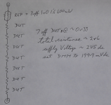
I showed in post1006 that the total resistance was ~2r6
and suggested a Vsupply of 2V5dc (it should have shown ~0.25V)
Then you MEASURE the REF Vdrop to determine the TEST current.
You could use ~0.5V for the supply and then measure the TEST current.
Or you could use ~1V for the supply and then measure the TEST current.
But if you go that high, ~400mAdc, then dissipation through the REF becomes high enough that a accuracy may be impaired. OK for "matching" of DUTs but a 12 resistor REF consisting of 6 parallel 1r0 1% 250mW PLUS 6 parallel 1r0 1% 250mW gives the same 0r333 and Pmax has gone up to 12*250= 3W, more than double what the 3off 1r0 600mW could manage.
The advantage of higher supply voltage is that the Vdrop is also higher. If your have a 2000 count DMM, you get more resolution if your test measurement is closer to the maximum of the 2000 count.
Builders with 4000 count or 40000 count DMM are fortunate that meter accuracy does not limit all practical matching accuracies.
My 50000 count bench DMM allows better than 0.01% for matching. But only if the measurement I am reading approaches the 50000 count resolution. I only very rarely need that, 2000 count allows better than 0.1% matching.
Last edited:
I used a small 2A transformer. I soldered in series one 10R 1% mf, and six 0R33 resistors. I measured 1.95V across the 10R resistor. I then measured across each of the 0R33 resistors and got between 64.5 and 66.5mV each. If my calculations are correct, that puts them at 0R33 to 0R34 which is pretty good for what I'm using them for.
Thanks for the tip.
Thanks for the tip.
your 10r 1% mf is running at 380mW.
That is hot.
OK for matching, but not OK for accurate REF.
It's too hot.
Put 10 off 10r in parallel for 1r0 equivalent and then use that original 10r to limit the current to your chosen value.
the string is now {power resistor to limit current} + REF + DUT +.... + DUT
BTW,
the 64.5 to 66.5mV gives a matching range of 3.1% for the whole group. It's easy to pick out matching pairs, or triples, or quads for future use.
Have you read about the Hamon divider?
Great tool for accurate ratio division.
Last edited:
I used a 1w 10R resistor. It didn't get hot I felt it before proceeding. This worked fine for what I needed to know which was whether of not these resistors were close enough in tolerance to give me an accurate enough idea of the bias. I tested a dozen and they were all in that range. I was glad to see it since I bought 100 of them.
- Home
- Amplifiers
- Solid State
- SX-Amp and NX-Amp