I use the 4-10 crest factor or 12-20dB. If 20dB has been measured on uncompressed music, I would want a little extra reproduction for headroom to stay clean sounding even on high dynamic range recordings.
Though most of the sound character or quality come from low power reproduction level information, the 20+dB extra power is needed to prevent clipping and its harmonic generation.
The amplifier cost goes up a lot when you have to accommodate high dynamic range recordings, cleanly.
Reducing the dynamic range thru compression methods may be (?) the lesser of the evils compared to clipping, blown tweeters and even greater annoying distorted sound..... Compressed can play loud enough without the high cost of a higher power amp needed for high dynamic range. After all, most street people (non-audiophiles) only think more power means louder and not about cleaner sounding.
[BTW --- what can be heard depends on at least the speaker distortion characteristics. I use the Quads sometimes. You need distortion well under these to be unknowable...... until -80 or .01%]

Quad speaker via Stereophile magazine tests
THx-RNMarsh
Though most of the sound character or quality come from low power reproduction level information, the 20+dB extra power is needed to prevent clipping and its harmonic generation.
The amplifier cost goes up a lot when you have to accommodate high dynamic range recordings, cleanly.
Reducing the dynamic range thru compression methods may be (?) the lesser of the evils compared to clipping, blown tweeters and even greater annoying distorted sound..... Compressed can play loud enough without the high cost of a higher power amp needed for high dynamic range. After all, most street people (non-audiophiles) only think more power means louder and not about cleaner sounding.
[BTW --- what can be heard depends on at least the speaker distortion characteristics. I use the Quads sometimes. You need distortion well under these to be unknowable...... until -80 or .01%]
Quad speaker via Stereophile magazine tests
THx-RNMarsh
Last edited:
Richard,
I guess that distortion plot was done at 1 watt output. In which case the resistor self heating would also be concomitantly lower.
The quads are remarkably low distortion but like most speakers, when you push them, distortion rises very quickly (the Quads perhaps a little less so than more conventional ones).
A agree with your comment about dynamic range. I use my sx-Amp with my B&W 703's (89 dB/W) and can get good volume out of them. But, ideally this amp should be paired with higher sensitivity speakers - eg 96 dB/W
Last edited:
I wonder if for the gerbers if some through hole plating and top side pads could be done.
I did not get around to doing version 3 this week end. Will try this coming weekend.
Hi,
I have those newer Quads and the distortion remains pretty low to fairly moderate levels..... But the point was that >.5% is not be the standard any more. I put them in when I want to hear the finest of details and resolution.
But my usual listening speakers use Cerwin Vega high efficiency pair of 15 inch on each side. driven by 250W/8 amplifiers. No compression nor clipping. Got bass?
THx-RNMarsh
My question was purely technical and genuine. I apologise for embellishing it with Golden Pinnae language.Your post does not deserve an answer, but I give you one anyway.
I did not say "evil".
But now it appears you are more interested in the Golden Pinnae embellishments than in the technical issues.

BTW, I was attempting a decadent Western joke. But will you answer the technical question?
Hello Wahyu,
Unfortunately, I am having problems with my internet, so cannot check the specs of the output devices you are proposing.
For the VAS devices, you really must use the recommended types (or very close equivalents). These have low Cob, low base storage - both of which are important for the linearity and amplifer behaviour as it exits clipping.
I will comment further when I can see the data sheets.
PCB rev.....
Maybe some guys ,want to make PCB and I hope I can help a little ......
Regards,Alex
Maybe some guys ,want to make PCB and I hope I can help a little ......
Regards,Alex
Attachments
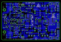
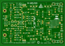
Maybe some guys ,want to make PCB and I hope I can help a little ......
Regards,Alex
Alex the PCB king!!
If you run a batch, I will surely take a stereo set
Thanks
Do
Hi Andrew,
While reading on your website it dawned on me that you have already released gerbers for a double sided sx amp. Sorry to have caused you any extra work. I think I am just going to try etching the single sided boards and go from there.
Thanks, Terry
Terry, that's great - look forward to seeing your results.
Maybe some guys ,want to make PCB and I hope I can help a little ......
Regards,Alex
That's fantastic Alex - thanks for doing this. I will also upload onto my website this weekend.
Maybe you want to do a board for the nx-Amp single sided with same tranny and mounting hole locations?
. Sure would be welcomed by the guys that want to etch their own and/or want to try the nx in single sided format with the sx single sided layout.
Last edited:
Hi Bonsai,
On the PSU, R5 and R8 are 22K resistors but I ran out of 22K and don't want to pay 8$ shipping for 0.50$ purchase... I wanted to know if the value is critical to be at 22K or if 21K 1/4W would be fine?
Thanks
Do
Hello Pinnocchio
These are the gate pull down resistors. They are not critical. 21 k will be fine - you can use 27 k or 18 k as well.
The offset on both the nx and sx amps is about 1-2 mV when warmed up. The reason for this is that there is first order cancellation of thermal effects due to circuit arrangement. The remaining Vbe deltas are then very small and cancel out once the front end reaches thermal equilibrium. Running both the buffer and the level shifters at the same collector currents also helps.
On switch on the offset is about 40-50 mV, but this settles to under 10 mV within about 2 minutes, and to under 2 mV after 3-4 minutes.
This is good performance for a non servo'd, DC coupled amp.
On switch on the offset is about 40-50 mV, but this settles to under 10 mV within about 2 minutes, and to under 2 mV after 3-4 minutes.
This is good performance for a non servo'd, DC coupled amp.
Last edited:
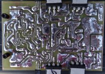
Hi Guys,
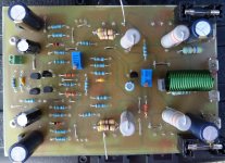
I etched some boards for the sx based on the files that Alex attached in post #971
I am having some issues. I used the values on the screen print except for using MJL4281/4302 for the outputs and 2SA130-Y/2SA3423-Y for the drivers since I had them in the same grade. Also the screen print calls for a BC547C in the vbe so that is what I used.
First off, I had to put in a 2K trimmer just to get the bias down to 500mv across the pair of .33R resistors and that is with the pot set for 2K. I am attaching a schematic with the voltages Andrew said to expect and a in purple what I am getting. Any help will be appreciated.
Thanks, Terry
Attachments
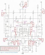
Terry,
Wow - that was a fast build!
The voltages you are showing around the schematic are within range - the 0.5V across the degen resistors gives you a shade over 1.5A total Iq - its ok.
For your bias adjustment, I suggest you leave it at 1 k and instead raise R20 (currently 220 Ohms) to 1 k or 1.2k.
I have to admit I did not set the pot to the mid position to see what the out Iq was - I would need to open up and measure.
The current across R32 and R33 is a bit higher than the 1V I show - the 100 Ohms Q9 and Q11 emitter degen resistors can be raised to 110 or 120 Ohms BUT I would just leave them as is and only change R20 as described above.
Make sure the output devices and the VAS transistors are well heatsinked - this amplifier runs hot - with 20-22V rails the standing dissipation is in the order of 60W. You need 0.4W/C worst case - 0.3W/C is what I recommend.
Look forward to your feedback on the sound.
- Home
- Amplifiers
- Solid State
- SX-Amp and NX-Amp