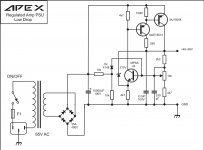
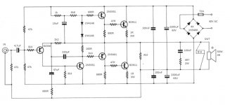
Well the two sine wave sources out in the middle of the amp are certainly unique. V1 & V4? Where were you going to buy those? I find sine wave appliances are usually >$100, I use $20 FM radios with an earphone jack turned down instead.
181 wires instead of 61 hardly qualifies this to be built in bare wire on bare board.
And what component keeps your $250 woofer (L3?) from melting the coil or ripping the surround if one solder joint pops loose? C7? 1000 uf. Isn't that impedance rather high at say, 54 hz? About 3 ohms? Series C18, 8 uf or @ 54 hz 373 ohms? I use 54 hz because that is the frequency where my $699 speaker rolls off down 3 db from average response.
Besides which R1 C1 would short off audible frequencies except subsonics.
L1 is the RF trap to keep AM sports talk radio out of your feedback? 3.3uH? Seems a bit small, .8mH or 800 uH is what Peavey used in my PV-1.3k amp.
Last edited:
Well the two sine wave sources out in the middle of the amp are certainly unique. V1 & V4? Where were you going to buy those? I find sine wave appliances are usually >$100, I use $20 FM radios with an earphone jack turned down instead.
181 wires instead of 61 hardly qualifies this to be built in bare wire on bare board.
And what component keeps your $250 woofer (L3?) from melting the coil or ripping the surround if one solder joint pops loose? C7? 1000 uf. Isn't that impedance rather high at say, 54 hz? About 3 ohms? Series C18, 8 uf or @ 54 hz 373 ohms? I use 54 hz because that is the frequency where my $699 speaker rolls off down 3 db from average response.
Besides which R1 C1 would short off audible frequencies except subsonics.
L1 is the RF trap to keep AM sports talk radio out of your feedback? 3.3uH? Seems a bit small, .8mH or 800 uH is what Peavey used in my PV-1.3k amp.
I hope you know, that this schematic is screencaptured of a simulation software. so thats why v1 and v4 is needed. For reading, V1 is just a 140Vdc supply, V4 cou can ignore.
Rlast, C18 and L3 is just a load, to simulate complex loads. so, just see as all thre components as speaker load - its all transformed into khz. This amp does also very well the hole audiorange. Sorry that you get confused by it.
the 3.3uH is in nearly every amplifier - in general in the range of 1 to 5uH.
Of course I said, that i will use it for a subwoofer, but this amp and this schematic is plays the hole audio range.
as simulation shows, the amp is very stable at all loads. Of course, real life is harder

The power supply will be not regulated of course.
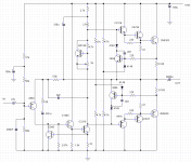
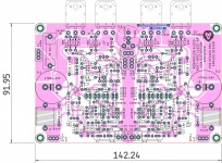
My take on a single supply retro amp (not the big one that runs on 120VDC). Just finished building it. Power supply is a 48V/4A transformer, brick rectifier, and 10,000 uF (powers 2 channels). Triple emitter follower output and enhanced VAS, but other than that a 'normal' topology. SOA protection was added. Used TO-3 output transistors that were just laying around. Most 80V or better epi-base types would work.
Attachments
Excellent progress wgski
One wonders where in North America you bought 2sa916, 2sa992, 2sa1837, 2sc945, 2sc2316, 2sc4793. Not newark, mouser, digikey, arrow. I just checked them. digikey shows some of the toshiba parts as "obsolete". I found some ksa992 & KSC1845 at mouser a couple of years ago but it took 6 months to receive the order.
If I were building it out of parts one can actually buy, I would use MPSA06/56, MJE15028/29, and MJL4302/4281. I'm using a TO220 D44R4 with 30 mhz Ft for VAS in my Apex AX6 and it doesn't hurt high frequency a bit compared to RCA40409 (TO5) on the ST120 channel. I found 2n3904 a bit fragile in djoffe's bias control circuit,blew a couple, kind of given up on them in areas over 35 v.
If you want to hot rod this to 2 pairs output, I bought a 44 vac 7 amp single winding EI transformer from ebay last year. It was real. They are still available New Hampshire Transformer Co., P-10814, Xfmr, 120/240 Vac To 44 Vac, 7.0 Amp | eBay
Last edited:
Where did I get the parts? Lifetime buys about 3 or 4 years ago. The drivers do seem to be still available even though obsolete - but nearly any new or vintage Jap drivers can be used. Use whatever Sanken or Toshiba is making nowadays or MJE1503x. Fairchild was still making A916/C2316 as of a few months ago. But MPSA06/A56 could be used. You would want a small clip on heatsink on the VAS. A vintage TO-39 would be another possibility. Old video output (CRT drivers) make fantastic VAS trannies. With the beta enhancer you don’t need the highest gain widest bandwidth device on the planet. Just not something with a 50 pF Cob.
Most of the other tall TO92’s are “gone”, but they are really still around if you look hard enough. All the old Sanyo TO92+ and TO126 are still around in the TO251 (leaded) and TO-252 (surface mount version) from ON - with new part numbers. But that package has a metal tab and no mounting hole, making it harder to fix to an output transistor heat sink. I guess they just want you to use epoxy.
Most of the other tall TO92’s are “gone”, but they are really still around if you look hard enough. All the old Sanyo TO92+ and TO126 are still around in the TO251 (leaded) and TO-252 (surface mount version) from ON - with new part numbers. But that package has a metal tab and no mounting hole, making it harder to fix to an output transistor heat sink. I guess they just want you to use epoxy.
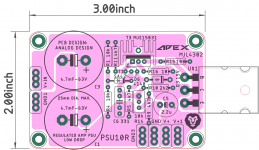
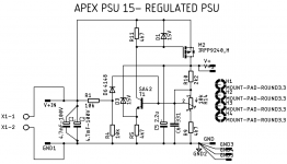
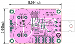
LDO regulated PSU for retro amp.
Mr. Mile, can we use single psu to supply to 2 channels?
Mr. Mile, can we use single psu to supply to 2 channels?
Yes
Thanks Mr. Mile,
here is compact single rail adaptation. It might be useful for an amp like MJR7-MK5 for which I am making layout.
regards
Prasi..
Nice work, also you can use mosfet like in PSU15.
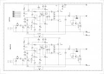
Here is a version of layout of MJR7-MK5 by Renardson Audio. The layout is inspired by the original design but slight tweaks here and there.
MJR7-Mk5 Mosfet Power Amplifier
Something like APEX 15R regulated PSU might be useful here?
regards
prasi
MJR7-Mk5 Mosfet Power Amplifier
Something like APEX 15R regulated PSU might be useful here?
regards
prasi
Attachments
Here is a version of layout of MJR7-MK5 by Renardson Audio. The layout is inspired by the original design but slight tweaks here and there.
MJR7-Mk5 Mosfet Power Amplifier
Something like APEX 15R regulated PSU might be useful here?
regards
prasi
Dear Prasi,
Beautiful Left-right symmetrical layout !
Can I request you to also provide a PCB layout for a single channel, with FET mounting distance = 4.0 in, mounting against a heatsink with Power FETs on either side of the PCB ? Size 3.5 in*3.5 in ?
--gannaji
Amp without output cap.
50W/4 ohms with 40V simple supply? will be?
Dear Prasi,
Beautiful Left-right symmetrical layout !
Can I request you to also provide a PCB layout for a single channel, with FET mounting distance = 4.0 in, mounting against a heatsink with Power FETs on either side of the PCB ? Size 3.5 in*3.5 in ?
--gannaji
Dear Annaji, pcb designing is actually my business. so if you need something specific, we can take further up via pm.
All my posted designs here on diya are free ( except GB's) and i make them for my own hobby. So you are welcome to ask for pdfs/ gerbers for any of the designs posted here by me.
regards
prasi
Hi Prasi,
Is there a Gerber posted for the titled amp in this thread? I looked quickly though and see mostly pdf for home etching. It looks like an interesting amp to try. Hopefully the usual 2SC5200N/2SA1943N can be used instead of the old school TO-3’s which are a pain to install. Hope all is well in your part of the world with the lock down.
Thanks and stay safe!
X
Request moderators to delete schematic from post no. 332.
Here is the corrected schematic.
The stuffing guide and pcb and the bom is correct and remains same. These too are attached herewith for completeness.
regards
prasi
hello x, thanks, we are not doing too bad... under complete lockdown.
Here are the gerbers for the apex ax-6 single supply amp. yes, i designed it for to-247/264 type output devices. I think i have spare pcbs but no shipping in sight...
the above quoted post gives the schema , pcb, stuffing and bom.
Take care of yourself...
regards
prasi
Attachments
- Home
- Amplifiers
- Solid State
- Retro Amp 50W Single Supply