Can i use this simple power supply with an 80VAC transformer to power the AX6 without changes?
Changes for 80V AC input.
Attachments
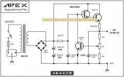
The circuit is fatally flawed in several ways; the worst flaw is that the 2N3773 will most like burn out instantly when the circuit is first powered up.
This will happen because the output is loaded with a 10,000 uF capacitor, which is fully discharged at turn-on, and acts like a short-circuit straight across the output at that first instant after turn-on.
There is no current-limit protection circuitry, so the 2N3773 has nothing to limit current through it except the tiny 0.22 ohm resistor connected to its emitter.
The output from the bridge rectifier will be about 110 volts; the 0.22 ohm resistor will therefore limit current to 500 amps. Result, the 2N3773 will burn out immediately when the circuit is turned on.
Most likely, depending on whether the base-emitter junction of the 2N3773 fails open or shorted, the MJE15030 will also burn out a millisecond after the 2N3773.
A high-power linear regulator is a very bad idea to start with, as Kay Pirinha politely pointed out. This particular circuit is even worse, as it will fail immediately due to overcurrent, even before it even has time to fail by overheating.
-Gnobuddy
The circuit is fatally flawed in several ways; the worst flaw is that the 2N3773 will most like burn out instantly when the circuit is first powered up.
-Gnobuddy
There is an RC on the input to the regulator to bring up volts slowly.
However, 10,000uF on output is still over the top.
Fold-back current limiting could (should) be added. And probably two 3773 in parallel.
The 10,000 uf would be needed so you do to have to set the current limit at 3X just to keep it from tripping on every cycle. And you want a back biased diode across the power transistor to keep from blowing it with the output cap charge if the input voltage collapses.
Far better use would be a 113 volt amplifier in the first place. Single supply operation at those voltages is possible, but you do want more than unity gain at DC in the amplifier loop. That way the bias at the Input transistor is lower, and transient voltages developed on your input coupling cap can’t get dangerous for what it is hooked up to.
I use a 3300 uf capacitor. For 2 boards. Got 72 watts into 8 ohms out of each simultaneous for 5 seconds on Rhianna Shut Up & Drive.
I also use 5 parallel TIP147 to regulate from 75 v to 69, with .5 ohm emitter resistors for sharing. The heat sink is 30mmx 50 mm x 130 mm off a dead Pentium 2 mainboard.
I frequently find no-center tap transformers on e-bay. Bought a 44 vac 7 A one last fall. That's about 63 vdc unloaded. Don't know about the surplus market in Brazil, but they are selling off factories in the US by the pound. Nothing needs to be made here but hot food, the Lords of Commerce have decided.
For triac regulator, you use triac to turn on shut off primary to transformer. Use comparator like 393 to turn on at low voltage, turn on at high voltage. use 74hc74 to remember what is going on now. Requires auxillary 12-30 v dc. Turn ons may pop, turn off is at zero crossing of AC voltage. SS relays can be bought that turn on and off at zero crossing.
Last edited:
In a relative sense, in the grotesque world we're discussing, I agree.Far better use would be a 113 volt amplifier in the first place.
But 113V is roughly a 200 watt (RMS) amp into an 8 ohm load. Peak speaker currents at full output power are around 7 amps, RMS speaker current around 5 amps. Does anybody really think it's a good idea to run 5 amperes of AC speaker current through an electrolytic cap (the speaker coupling cap)?
I can (just barely) understand that someone might want to build a 10-watt amp like this just for the fun of a long trip down memory lane. But as the power levels go up, so does the expense and the level of impracticality. At some point it becomes a perverse exercise in silly engineering, rather like trying to build a hamster-powered moon rocket.
-Gnobuddy
Its not complicated you hold the gate at the desired voltage I will get a schematic over onto the forum over the weekend It really a derivative from Arthur Baileys original Radford SCa30 amplifier you need a large resistor a zener a few diodes and a decent thyristor
Brilliantly simple
Trev
Brilliantly simple
Trev
It is a 70 watt amp (5 seconds at a time) from 70 v PS. 2 MJ15003/channel. With speakers that cost $700 apiece and an amp that costs $100, I seriously do not want DC to destroy my speakers. I have enough solder joints pop loose DC on speaker is a serious hazard. As do most amateurs.I can (just barely) understand that someone might want to build a 10-watt amp like this just for the fun of a long trip down memory lane. But as the power levels go up, so does the expense and the level of impracticality.
99% of the DC protection circuits on ebay/amazon/alibaba are snake oil. RJ Keene double nfet speaker disconnect is great in theory, but nobody on ebay/amazon/ali is selling one to my knowledge. Don't know of any commercial amps that have those, either. You buy a serious proven disconnect relay from peavey,crown, QSC, you're out $100 for two. 99.99999% of all hard contact relays on the market are AC contact rated, not for DC arcs. Two 3300 uf caps is $8. Which passed my 72 watts. Don't recommend poster use his 80 v transformer.
At a previous employer we used to put DC on refrigerator compressors to cause the overload to trip. The contactor we used had 11 mm diameter contacts. We replaced those contacts twice a year during shutdown. Each contactor was about $600 new in 1985. That contactor might break a 500 A arc reliably @ 170 vdc, the open distance between contacts was about a centimeter.
For beach bars this amp is ****, it won't do 70 W 24/7. It will do about 5. For classical music with low crest factor, it does fine with average power of 5 and peaks of 70 W when the cannon goes off in 1812 overture. It is also one of the lowest wire count amps I've ever seen, which if one is not buying pc boards from the sole source *****, makes this doable point to point.
Last edited:
At some point it becomes a perverse exercise in silly engineering, rather like trying to build a hamster-powered moon rocket.
-Gnobuddy
ha ha ha ha - brilliantly explained! 😀😀😀 I WILL remember that one!
Thanks!ha ha ha ha - brilliantly explained! 😀😀😀 I WILL remember that one!
Twenty-odd years ago I had a colleague who was asked to design and prototype a class AB power amp for a powered speaker project. After looking at size, price, and timeline, he leafed through the National Semiconductor catalog, found a nice chip amp, etched his own PCB, and built the amp.
The marketing guys listened to it, and said "Not loud enough. Make it louder."
The chip was nearing its power limit, but National said you could put two in parallel for twice the power, so my friend re-engineered the PCB, built the two-chip amp, and gave it to the marketing guys for a second test.
Yup, it came back with "Not loud enough. Make it louder."
My friend built the next iteration: four of the same chips, now in parallel bridge mode. Finally, it was loud enough.
But: at four times the original cost, four times the PCB area, four times the heatsink size and weight, four times the complexity, four times the parts count, and harder to make stable.
Basically it was now a silly design, because the marketing guys had moved the goal posts so far from the original design specs. The design my friend started out with made sense; but along the way, it had gradually evolved into a ridiculous thing held together with Band-Aids and rubber-bands.
If my friend had originally been given the proper spec, he would never have started off with that chip amp; he'd probably have whipped up a discrete design, since that chip was already the limit of how much power you could put in a little TO-220 package. And it would have been elegant and well designed, because my friend was a good engineer.
Sometimes I find my own personal electronics projects starting to go down that same road, evolving from an original elegant ideal towards extreme complexity and silliness - and I try to be aware of that phenomenon, to pull back, shake it off, and start down a more sensible path.
-Gnobuddy
I understand the pros need stuff like this - if you have a paying audience listening, you do not want a misbehaving speaker disconnect.You buy a serious proven disconnect relay from peavey,crown, QSC, you're out $100 for two.
I understand the issue with self-welding disconnect relays, too. That's no good, when you really need the silly thing to disconnect.
But I don't do pro audio for paying customers. For my own home use, I would probably just solder a 0.1 ohm, 1/4 watt carbon film resistor in series with one speaker, and call it good.
That resistance value allows 10 watts RMS into an 8 ohm speaker before the resistor reaches its dissipation limit and starts to burn up, and 0.1 ohms is far too low to matter as far as speaker damping factor goes. And a 0.1 ohm, quarter-watt resistor is dirt cheap!
-Gnobuddy
In a relative sense, in the grotesque world we're discussing, I agree.
But 113V is roughly a 200 watt (RMS) amp into an 8 ohm load. Peak speaker currents at full output power are around 7 amps, RMS speaker current around 5 amps. Does anybody really think it's a good idea to run 5 amperes of AC speaker current through an electrolytic cap (the speaker coupling cap)
-Gnobuddy
i just got done with a build of exactly that - for the reason that it is DC fault proof. It’s 150 watts per channel at 8, and calling it the “AC300A”, because of its topological and physical resemblance to the famous Crown. uses an old 80V 8A EI core Triad. The caps can take it - they are 7800uF 200 volt screw terminal soup cans. In most sane uses, the RMS current through the caps isn’t really all that high, an amp or two on average when playing loudly. The reservoir cap ends up with about the same ripple current anyway. Soup cans can take 10 amps when I’m playing around with it on the bench driving who-knows-what with sine waves.
Classical music has 55 db dynamic range on LP. 72 on CD.But I don't do pro audio for paying customers. For my own home use, I would probably just solder a 0.1 ohm, 1/4 watt carbon film resistor in series with one speaker, and call it good.
That resistance value allows 10 watts RMS into an 8 ohm speaker before the resistor reaches its dissipation limit and starts to burn up, and 0.1 ohms is far too low to matter as far as speaker damping factor goes. And a 0.1 ohm, quarter-watt resistor is dirt cheap!
-Gnobuddy
20log.125W=-18 db. 20 log64w is 36 db. So an ax6 will reproduce 54 db dynamic range if you start at 1/8 W for pp passages. I measured 1.5 Vpp one time on a soft passage on the "8 ohm" speaker.
I don't intend to throttle my amp to 10 w or 20 db , or 38 db dynamic range. I do intend to not burn up my $700 each speakers with DC. About equivalent to my food bill for 4 weeks. Which DC could easily happen except $4 caps are pretty reliable DC blockers, for 10-15 years anyway.
I've got a CS800s I paid about $100 for that would do the 72 db dynamic range, with a serious speaker disconnect on DC Enzo told me. Only left channel drops in and out. Seems Peavey doesn't make perfect solder joints either. Just no DC out of this unit. Next winter I'll chase that problem, not now.
Last edited:
But I don't do pro audio for paying customers. For my own home use, I would probably just solder a 0.1 ohm, 1/4 watt carbon film resistor in series with one speaker, and call it good.
That resistance value allows 10 watts RMS into an 8 ohm speaker before the resistor reaches its dissipation limit and starts to burn up, and 0.1 ohms is far too low to matter as far as speaker damping factor goes. And a 0.1 ohm, quarter-watt resistor is dirt cheap!
-Gnobuddy
Exactly what I did for a friend back in college - to get his roommate to quit messing with his stereo. Turn it up too loud and smoke comes out and the sound quits. Cured it the first time.
- Home
- Amplifiers
- Solid State
- Retro Amp 50W Single Supply