... a new member for my measurement "park" ...
That looks very nice, I have not seen Sourcetronic.
And coincidentally I just sent you an email.
Best wishes
David
Last edited:

Dear keantoken,
this is what I like as diyaudio fan. We help together to get better amps, have fun on math, simulations, modeling and real life testing.
Will do and report tomorrow some better data in your 6145/2223 sanke thread.
Quicktested the 2SA2223A: below 25kHz the display of the series R is wonky. Above 25k it stays nearly same ...
BR, Toni
Last edited:
I could rack up an incredible number of hours spent on those models if we keep revising them. Not sure I want to do this forever.
What is the R value given when Cbe is tested?
The Rb in the 2223 model is fairly close, changing the 6145 model may mean deviating from the datasheet Vbe curve.
What is the R value given when Cbe is tested?
The Rb in the 2223 model is fairly close, changing the 6145 model may mean deviating from the datasheet Vbe curve.
... a Cbc measurement of Sanken 2SA2223AY using 10mV/100kHz test signal. (Cjc space charge capacitance at vBC=0V)[/QUOTE]
Hi Astx") ,
,
I did check your values on my bridge, and here are the successive values as I did get them that I did find at 5mV and 100kHz :
933.33 pF and 58.9 Ohm Avg 10 times 2SC6145AY
1.6478 nF and 23.1 Ohm Avg 10 times 2SA2223AY
933.95 pF and 58.5 Ohm Avg 10 times 2SC6145AY
1.6493 nF and 23.1 Ohm Avg 10 times 2SA2223AY
I have found that the Rs value dipends on the V of the measurement : at 10 mV I find lower Rs values : around 32 Ohm and 15 Ohm.
Thanks for the reference of the Hand Tapper made in China you did give to us : I did get one and it is a great tool that works fine !
Best regards
rephil
Hi Astx
,I did check your values on my bridge, and here are the successive values as I did get them that I did find at 5mV and 100kHz :
933.33 pF and 58.9 Ohm Avg 10 times 2SC6145AY
1.6478 nF and 23.1 Ohm Avg 10 times 2SA2223AY
933.95 pF and 58.5 Ohm Avg 10 times 2SC6145AY
1.6493 nF and 23.1 Ohm Avg 10 times 2SA2223AY
I have found that the Rs value dipends on the V of the measurement : at 10 mV I find lower Rs values : around 32 Ohm and 15 Ohm.
Thanks for the reference of the Hand Tapper made in China you did give to us : I did get one and it is a great tool that works fine
!Best regards
rephil
Dear rephil,
my LCRZ measurements Cs-Rs results are relatively independent from test signal 10mV up to 190mV (where the bjt diode starts conducting a bit) e.g. for the 2SA2223AY Rs is about 3R at 10mV and slighly reduces a few percent up to 190mV test signal.
From 25kHz up to 100kHz the values are also stable within a few percent.
Maybe your LCR isn't able to go as low as needed. Your measured Rs values are more as 10 - 20 times higher as my results.
My new LCRZ regulates the output impedance automatically from 3 Ohm to 30 kOhm and works even if you apply an external bias voltage.
Take some small capacitors and increase the test signal level from 10mV up to 2 Vrms.
E.g. use a Wima 10nF MKP10 630V. The Rs should stay same at same test frequency (100kHz) during test voltage sweep. I measure 0.11R
BR, Toni
P.S.: about hand tapper: you are welcome!
Last edited:
Dear keantoken,...
What is the R value given when Cbe is tested?
...
will do some more testing and present you the data in the 6145/2223 thread from you. Thx so much for supporting us diy'ers with optimized models!
BR, Toni
Dear rephil,
my LCRZ measurements Cs-Rs results are relatively independent from test signal 10mV up to 190mV (where the bjt diode starts conducting a bit) e.g. for the 2SA2223AY Rs is about 3R at 10mV and slighly reduces a few percent up to 190mV test signal.
From 25kHz up to 100kHz the values are also stable within a few percent.
Maybe your LCR isn't able to go as low as needed. Your measured Rs values are more as 10 - 20 times higher as my results.
My new LCRZ regulates the output impedance automatically from 3 Ohm to 30 kOhm and works even if you apply an external bias voltage.
Take some small capacitors and increase the test signal level from 10mV up to 2 Vrms.
E.g. use a Wima 10nF MKP10 630V. The Rs should stay same at same test frequency (100kHz) during test voltage sweep. I measure 0.11R
BR, Toni
P.S.: about hand tapper: you are welcome!
Hi Toni
,I have bad news (for me) : I did check at first my LCR before doing the test you are suggesting : it is a GWinstek LCR model 819. So, I have seen after recalling the calibration factory set up that at first the internal battery should be changed
. With the reloaded factory settings, I did repeat the measurement I did do with the same transistors. Now the Rs is mostly 6 Ohm and 4 Ohm at 10mV, 5mV and both at 100kHz. I apologize with you for the values I did provide here. The internal battery will be changed, and I wil let perform a calibration of the instrument by authorized people (after 10 more years, it should be done ). I have now to find out who could do that in Belgium for me, people being able to perform that well ! Please nobody should consider the measurement values I did provide, these have been done with a very good LCR meter that is today in need of help ... Sorry
for that.Best regards - Mit freundlichen Grüßen aus Belgien
rephil
Dear rephil,
thanks for reporting this. Hopefully you get your LCR re-calibrated. Isn't there a procedure you can do yourself? Maybe you only need to buy some known parts to do a minimum setup?
BTW: found a pdf for recalibration, but you need additional measurement parts and devices: http://www.produktinfo.conrad.com/d...an-01-en-LCR_Meter_817_Kalibrieranleitung.pdf
BR, Toni
Last edited:
Dear rephil,
thanks for reporting this. Hopefully you get your LCR re-calibrated. Isn't there a procedure you can do yourself? Maybe you only need to buy some known parts to do a minimum setup?
BTW: found a pdf for recalibration, but you need additional measurement parts and devices: http://www.produktinfo.conrad.com/d...an-01-en-LCR_Meter_817_Kalibrieranleitung.pdf
BR, Toni
Hi Toni
,Thank you for this very friendly help. I did see it too, but I will not use it as I don't want to buy other tools that I have no use. The calibration is somewhat I will let do buy professionals.
Have a nice day !
Best regards
rephil
@tubestrek
I will remind you now to do it :
In Italy people says that when you are young, you have teeth but no bread, and when you become old, you have bread but no more teeth ... My friend, buy when you are young (if your wife
 allows you to do that), and don't expect to use good instrumentation when you will be old : your health will not allow you to do that anymore
  !
!Have a nice day
Best regards
rephil
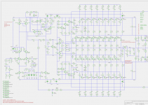
SA2019 - Going green - New Class H
I'm currently planning a new monster green amp (SA2019) with those specs:
+/- 85V rails, +/- 20V rails
450W@8R,900W@4R,1600W@2R
Idle power dissipation ~ 20W
The outer rails are driven by 8 pairs IRFP240/9240. To hold the gate resistance low I plan to add ferrite beads and like to ask you if you have experience using ferrite beads like the attached one.
BR, Toni
Attachments
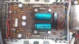
I don't think these beads act as reactances, i.e. increase the leads' inductances. This wouldn't suppress oscillations, but solely decrease their frequencies, and possibly lead to further instabilities imho.
The ferrite these beads are made of deliberately is a very lossy one. Hence possible resonant circuits are damped due to the losses. For this reason these beads were very common with tube technology, and I've also seen them yet in SS circuits. The pic, for example, shows the PSU/power amplifier of an old DUAL KA 60 console. Note the beads at the base leads of both left handed transistors.
So I think you might just try it. What could happen?
Best regards!
Attachments
- Home
- Amplifiers
- Solid State
- 2stageEF high performance class AB power amp / 200W8R / 400W4R