Thx!
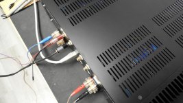
Cable length mostly fits. Only speaker cables are a bit too long - will be corrected.
Have fun, Toni
State of the art!

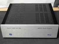
ASTX LABS - SA2017 VMOS IXYS
Thx!
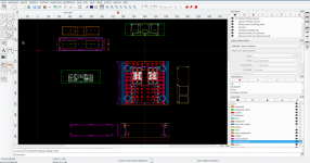
I'm using QCAD to design the case - so this case is completely custom made. For this amplifier the only part from modu.it is the brushed aluminium front panel.
All other parts are designed by me. CNC machining has been done mostly by
Thx!
I'm using QCAD to design the case - so this case is completely custom made. For this amplifier the only part from modu.it is the brushed aluminium front panel.
All other parts are designed by me. CNC machining has been done mostly by
- Schaeffer AG: Home and
- Home - Cutworks - DE (lasered steal parts).
- heatsinks are from www.cooltec.com and cnc-machined and anodized by Schaeffer AG: Home.
- Inner steal parts are powder coated by www.wolfmair.at
Attachments
Last edited:
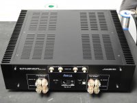
ASTX LABS - SA2017 VMOS IXYS - PROJECT FINISHED
... project successfully finished!
SA2017 IXYS MOSFET 4 channel is singing from first powering up.
No noise, hum, physical hum.
First noise measurements are indicating lowest noise - same as during tests of single modules on regulated supply / testbed.
Every channel has its own powersupply delivering 2x48V DC with a load of 250mA bias per amplifier. A powerful 800VA transformer does the 230V job.A longer run test showed that heatsink temperature doesn't go above 36 degree celsius (room temp ~ 23 - 24 degree). Inner temperature is about 29 degree.
Sound checked using ILLU18-8 monitor box (highend scanspeak illuminator beryllium tweeter [FONT=Arial, Helvetica, sans-serif]D3004/6640 [/FONT]and [FONT=Arial, Helvetica, sans-serif]mid/bass driver 18WU8741T) - a perfect sound stage.
[/FONT]Next projects can begin ...
[FONT=Arial, Helvetica, sans-serif]Have fun, Toni[/FONT]
P.S. for Kay Pirinha: grounding color changed to black
[FONT=Arial, Helvetica, sans-serif]
[/FONT]
[FONT=Arial, Helvetica, sans-serif]
[/FONT]
Attachments
P.S. for Kay Pirinha: grounding color changed to black
Well done, Toni
 ! As well as the entire unit!
Best regards!
Last edited:
Thx my friends! Wish you could be here for
Just tested with another pair of speakers at "full power" using my M50TL transmissionline speakers (see black stone case below on this homepage AOS - M50TL)
Chris Jones "Thank you" - deep bass - perfect. "Sanctuary" - perfect deep bass.
Piano: Keith Jarret, Diana Krall,
Dire Straits ... and many other test songs...
BR, Toni
Thx my friends! Wish you could be here for
Just tested with another pair of speakers at "full power" using my M50TL transmissionline speakers (see black stone case below on this homepage AOS - M50TL)
Chris Jones "Thank you" - deep bass - perfect. "Sanctuary" - perfect deep bass.
Piano: Keith Jarret, Diana Krall,
Dire Straits ... and many other test songs...
BR, Toni
I wish i would be there for listening experience, never i had the opportunity to listen diy amplifiers with top speakers

... project successfully finished!
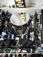
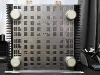
That is not only the nicest amp I have seen in DIY, but as nice as I have seen from any manufacturer.
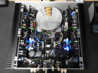
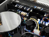
Is that your resistor test load reflected in the toroid cover?
Best wishes
David
... Is that your resistor test load reflected in the toroid cover? ...
Thx! Yes that's the test load to avoid destroying my expensive speakers...
And many thx goes to you (!) for supporting me with new MOSFET spice models for the used power transistors!
BR, Toni
Last edited:
ASTX LABS - SA2017 VMOS IXYS - PROJECT FINISHED
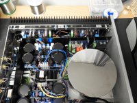
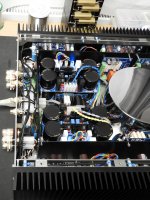
... some more photos ...
... some more photos ...
Attachments
ASTX LABS - SA2017 VMOS IXYS - PROJECT FINISHED
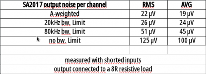
some noise measurements ...
Input cable routing is very important to get low noise on all channels. The routing is asymmetric as the amp modules are mounted different on left and right side. Obviously I have done it correct because low noise values compare to the amp during development phase.
More measurement values will follow.
BR, Toni
some noise measurements ...
Input cable routing is very important to get low noise on all channels. The routing is asymmetric as the amp modules are mounted different on left and right side. Obviously I have done it correct because low noise values compare to the amp during development phase.
- A-w S/N ratio is ~ 100dB compared to 1W@8R output power.
- DC-offset below 100mV.
More measurement values will follow.
BR, Toni
Attachments
Last edited:
HF noise and noise power distribution above 20 Khz or 80kHz is also an indicator of stability, oscillations, bad HF isolation ...
E.g.: using SMPS or fan's inside your amp with bad HF isolation you could see higher noise values than usual and fix this.
My SA2015 4 channel IFP240/9240 MOSFET is actively cooled and has a 1200VA SMPS inside. HF noise measurements helped to fix some minor HF isolation problems.
BR, Toni
E.g.: using SMPS or fan's inside your amp with bad HF isolation you could see higher noise values than usual and fix this.
My SA2015 4 channel IFP240/9240 MOSFET is actively cooled and has a 1200VA SMPS inside. HF noise measurements helped to fix some minor HF isolation problems.
BR, Toni
Last edited:
... project successfully finished!
Amazing project and finish! Chapeau!
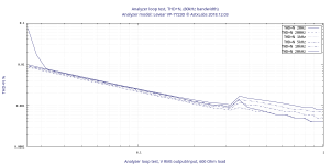
ASTX LABS - SA2017 VMOS IXYS - Measurements
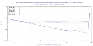
Attached some THD+N measurements for my newest "product".
SA2017-VMOS-AB4-800 100W IXYS MOSFET:
BR, Toni
Thx!Amazing project and finish! Chapeau!
Attached some THD+N measurements for my newest "product".
SA2017-VMOS-AB4-800 100W IXYS MOSFET:
- Channel A - Left
- Channel A -Right
- Channel B - Left
- Channel B -Right
BR, Toni
Attachments


Last edited:
Hi astx,
can you please show the analyzer chart with loop connector?
Dear Ralf,
making a loop plot of VP7723D analyzer itself with same output levels and therefore with very low input levels is hardly better as the shown results.
I have tested the analyzer loop with -32db to 0db output with 600R load which delivers a rms signal to the input like this table:
#20.2 HZ
# Hz DB Input Vrms THD+N
1 19.99000000 -32DB 0.02530000 0.07540000
1 19.99000000 -31DB 0.02830000 0.01680000
1 19.99000000 -30DB 0.03180000 0.00790000
1 19.99000000 -29DB 0.03570000 0.00670000
1 19.99000000 -28DB 0.03990000 0.00610000
1 19.99000000 -27DB 0.04470000 0.00540000
1 19.99000000 -26DB 0.05010000 0.00480000
1 19.99000000 -25DB 0.05620000 0.00430000
1 19.99000000 -24DB 0.06320000 0.00390000
1 19.99000000 -23DB 0.07080000 0.00340000
1 19.99000000 -22DB 0.07930000 0.00310000
1 19.99000000 -21DB 0.08900000 0.00280000
1 19.99000000 -20DB 0.09970000 0.00250000
1 19.99000000 -19DB 0.11170000 0.00222000
On analyzer I have to switch from balanced to single ended input with a direct connected coax cable to get the best loop test results.
If I compare the results of -19DB with the data line from output via amplifier:
1 20.02000000 -19DB 3.08400000 0.00195000
... think you can see the problem ... IMHO the notch filter works better with higher input signal levels and/or the analyzer internal input noise makes the difference ...
Thats why I said
Interpret the results as "better as".
especially in the lower power range < 10W. Don't forget the amplifier has a dual slope current protection active which slightly increases the distortions above 5kHz. But we still have comfortably two zeroes THD+N behind the dot ...
Thx!Very nice!
Have fun, Toni
Attachments
Last edited:
- Home
- Amplifiers
- Solid State
- 2stageEF high performance class AB power amp / 200W8R / 400W4R