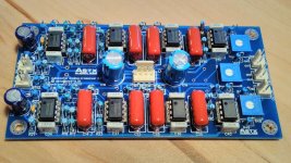
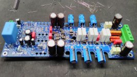
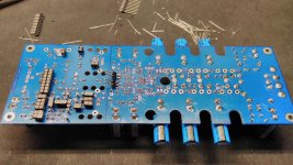
Off topic: LR24 subwoofer analog crossover - 2.1 system
... completely off topic: a linkwitz riley 24 dB analog crossover for a 2.1 outdoor party system.
(raspberry pi3, hifiberry dac+, subwoofer analog crossover, 3 x Hypex UCD180).
BR, Toni
... completely off topic: a linkwitz riley 24 dB analog crossover for a 2.1 outdoor party system.
(raspberry pi3, hifiberry dac+, subwoofer analog crossover, 3 x Hypex UCD180).
BR, Toni
Attachments
Last edited:
Ok I think this matches. Perhaps you can double check...
Pin1 - 4 order seems to be correct in respect to the housekeeping V4 pcb versions.
BR, Toni
...
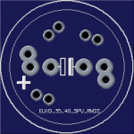
PS: can you send me the revised cap footprint?
Voila!
Note: pcb footprints are free to use only for non commercial DIY projects and non commercial pcb's.
BR, Toni
Attachments
... a linkwitz riley 24 dB analog crossover for a 2.1 outdoor party system.
BR, Toni
Is this circuit shareable?
Is this circuit shareable?
I'm unsure - think it is copyrighted. Most of the circuit and part values are from page 248 of the book of D. Self "The design of active crossovers" with some changes/additions from me. I have added a mono summer for the subwoofer channel and output buffers. These parts I can provide freely.
The LR24 circuit itself is downloadable from "rane":
http://www.rane.com/pdf/old/ac22ssch07.pdf
D. Self has reduced the LR24 relevant resistor part values by a factor of 4 and added a 10dB gain buffer in front of the circuit.
BR, Toni
Last edited:
I'm unsure - think it is copyrighted. Most of the circuit and part values are from page 248 of the book of D. Self "The design of active crossovers" with some changes/additions from me. I have added a mono summer for the subwoofer channel and output buffers. These parts I can provide freely.
The LR24 circuit itself is downloadable from "rane":
http://www.rane.com/pdf/old/ac22ssch07.pdf
D. Self has reduced the LR24 relevant resistor part values by a factor of 4 and added a 10dB gain buffer in front of the circuit.
BR, Toni
TYVM!
SA2016: using lateral mosfets ECW20N20 ECW20P20
... small progress ... had some time for preparations to test ECW20x20 double die Exicon lateral MOSFET's using +/-52V supply. Should be able to provide 120W@8R and 240W@4R ...
... small progress ... had some time for preparations to test ECW20x20 double die Exicon lateral MOSFET's using +/-52V supply. Should be able to provide 120W@8R and 240W@4R ...
Attachments
Hi Tony, FYI on copyright, I see you do not put any on your pcb designs. When I worked for the big guys, doing pcb layouts, it was a requirement that I/we put a copyright notice on the pcb, the symbol &/or the words "C" with a circle and the date, both in silk and in copper. Just a way to try to protect your IP and blatant copying. Not to say a gerber editor can remove the info.
Nice work as always.
Nice work as always.
Hi Tony, FYI on copyright, I see you do not put any on your pcb designs. When I worked for the big guys, doing pcb layouts, it was a requirement that I/we put a copyright notice on the pcb, the symbol &/or the words "C" with a circle and the date, both in silk and in copper. Just a way to try to protect your IP and blatant copying. Not to say a gerber editor can remove the info.
Nice work as always.
Dear Rick,
thanks for the info but now I'm a bit confused. Every selfdesigned pcb layout has my copyright information - the older designs in the simple form
(c) astx@...
on both sides as silk screen info and on solder side as copper traces...
BR, Toni
(for the above pcb have a look at the images here at post #1803:
http://www.diyaudio.com/forums/solid-state/235194-2stageef-high-performance-class-ab-power-amp-200w8r-400w4r-post4805477.html)
SA2016: using lateral mosfets ECW20N20 ECW20P20
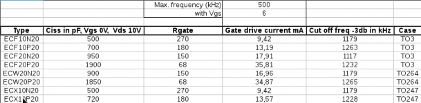
Gate resistor calculations:
Has anybody experience using lowered gate resistor values using double die lateral mosfets?
Attached a calculation table which compares the different gate resistors versus cut off frequencies.
BR, Toni
Gate resistor calculations:
Has anybody experience using lowered gate resistor values using double die lateral mosfets?
Attached a calculation table which compares the different gate resistors versus cut off frequencies.
BR, Toni
Attachments
Hi Toni
Since you have started to look at new MOSfets I wondered if you had considered the Verticals from IXYS?
They do a series intended for linear operation, so are properly specified for SOA at DC, unlike the IRF.
Maybe not double die, just enormous die, so substantial capacitance but substantial power capacity too, one IXYS would replace 3 IRFP perhaps.
Specs http://ixapps.ixys.com/DataSheet/DS100294(IXTH-TT80N20L).pdf
The closest complement seems to be
http://ixapps.ixys.com/DataSheet/DS99981CIXTH-T48P20P).pdf
Best wishes
David
I used the double die in the 2014 PCB, but never thought about changing the gate resistor values.Gate resistor calculations:
Has anybody experience using lowered gate resistor values using double die lateral mosfets?
Attached a calculation table which compares the different gate resistors versus cut off frequencies.
BR, Toni
Hi Toni
Since you have started to look at new MOSfets I wondered if you had considered the Verticals from IXYS?
...
Dear Dave,
interesting devices indeed. But can't find simulation models. IXYS has many spice models online but unfortunately not for these parts.
Will buy some samples for testing with a SA2015 pcb.
BR, Toni
P.S.: spice models wanted for IXYS vertical mosfets:
- IXTH80N20L (200V, 80A, 0.032Rdson)
- IXTH48P20P (200V, 48A, 0.085Rdson)
I used the double die in the 2014 PCB, but never thought about changing the gate resistor values.
The question is: will the double die mosfets be stable using such low resistor values: 150R for N-Channel and 68R for P-channel mosfets. The calculated cut off frequencies are nearly the same as the single die mosfets which are stable using 270R and 150R gate resistors.
Will test this on my modified PCB how low we can go in this design without oscillations...
BR, Toni
P.S.: of course you mean the SA2015 pcb's - do you?
")
OK - that was the pcb "SA2015 rev. 1.4 2016.06.17" - wrong named (name was reserved for the vertical mosfet "SA2015" amp) and with trace error but can be made working using a knife and is after-wards electrical identical with the corrected pcb "SA2016 rev 1.6.2 2016.08.07".I have the PCBs with the trace error, that you gave away for testing.
Many Alfet and Exicon circuit examples are showing 330R for N-channel and 220R for P-channel gate resistors for single die mosfets.
A double die chip has 2 times the Ciss and the questions is: will the mosfet be stable if we reduce the gate resistor to represent the same cut off frequency?
BR, Toni
P.S.: spice models wanted for IXYS vertical mosfets:
- IXTH80N20L (200V, 80A, 0.032Rdson)
- IXTH48P20P (200V, 48A, 0.085Rdson)
Ask on the LTspice Yahoo forum?
- Home
- Amplifiers
- Solid State
- 2stageEF high performance class AB power amp / 200W8R / 400W4R