... very much good tips to improve the design. Even AndrewT's "beginners knowledge" is important. Note: this amp is a very young red wine and needs some days/weeks to mature.
And don't forget - we are talking about distortion 0.00x % at 20kHz at 200W at 8R
")
AndrewT - I have not seen any amp design from yourself ...
And don't forget - we are talking about distortion 0.00x % at 20kHz at 200W at 8R
AndrewT - I have not seen any amp design from yourself ...
...
What are you using as a load when testing?
...
Load is multiple power 50W resistors which are minimum as awful as standard speakers...
you mean the 10R parallel to coil should be lowered?
I would recommend so, I have never seen such a high value used in a commercial design, but then again I havent studied many low and mid range amps. Some advocate to not use any resistor at all. This is a good opportunity for investigation, if you tried lowering the value and see the result in THD. This would clarify things for a lot of diyers, so youd be doing all a favour.
Personally I dont use coils in my amps and design for phase margins of above 80 so I can get away with just a 1 or 2 ohm resistor in series and the use of zobel network.
Hear! Hear!
Get your coil and its parallel resistor off the output PCB and as far as possible away from things like power-supply cables and anything made of iron or steel.
What are you using as a load when testing? Any non-linearity in the load will cause a non-linear current to flow which will then drop a non-linear voltage across the output coil and wiring, causing higher distortion readings after the coil.
During development THD figures where always measured at NFB takeoff point before output coil to minimize non linearity effects from load resistors (which have a relatively high inductive component as they are wire wound power resistors). Now on rerouting the speaker output cable I am nearly back to the lab performance. Will move the coil and resistor off the pcb to test the effect of different locations.
no !!!!
a single Flow or Return cable passing through a hole is not allowed. Does it make a current transformer? Or is it some other effect?
Both the FLOW and Return must pass through the same hole if it must through a hole at all.
But why have you got a single wire. It should be a twisted pair !!!!!!
That pair is both resistant to picking up interference and is good at not transmitting interference.
Always close couple Flow and Return Pairs. Always. That is what makes Planes good. The close coupling of the Flow and Return currents. In wire connections twisting achieve similar.
As the THD decreased dramatically on routing the speaker out cable below the mounting plate I think the "transformer" effect of this can be reduced to something like 2 ferrit beads.
What you can not see is that the speaker cable is routed as long as possible parallel/twisted with the corresponding return/ground cable.
Found the problem:
The small pcb where second zobel and output relais is mounted has had a contact from speaker ground to case which is subsubsubsuboptimal.
My fault: a simple pcb design error.
Now we have the wanted low thd at amplifier speaker terminals.
THD+N without load at amplifier speaker output terminals:
Thank you all for your help!
Now the final documentation has to follow so this amplifier can be rebuild very easy.
BR, Toni
The small pcb where second zobel and output relais is mounted has had a contact from speaker ground to case which is subsubsubsuboptimal.
My fault: a simple pcb design error.
Now we have the wanted low thd at amplifier speaker terminals.
THD+N without load at amplifier speaker output terminals:
THD21K@40V RMS
0.0016% (bw 80kHz)
THD1K@40V RMS
0.0005% (bw 80kHz)
THD+N with load at amplifier speaker output terminals:0.0016% (bw 80kHz)
THD1K@40V RMS
0.0005% (bw 80kHz)
THD21K@200W@8R
0.0024% (bw 80kHz)
THD1K@200W@8R
0.0015% (bw 80kHz)
WOW! 0.0024% (bw 80kHz)
THD1K@200W@8R
0.0015% (bw 80kHz)
Thank you all for your help!
Now the final documentation has to follow so this amplifier can be rebuild very easy.
BR, Toni
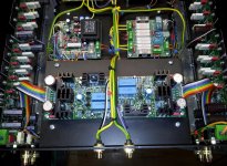
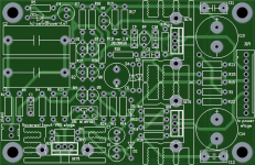
All above measurements are made with Rev 2.0 Input/VAS boards (see attached picture: mounted on top of the amplifier - far away from the toroids).
Grounding is here very important. A strong copper wire is directly soldered to ground connectors of chinch inputs and the other side is connected to left or right star ground.
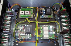
Second picture shows the dual star ground and all control circuits.
The speaker ground return is NOT connected to the main star ground - it is connected to the power supply star ground. The amplifier output stage positive, negative supply and ground wires are paralled
Amplifier output stage speaker output is separated and routed under the mounting plate to back of amplifier.
Grounding is here very important. A strong copper wire is directly soldered to ground connectors of chinch inputs and the other side is connected to left or right star ground.
Second picture shows the dual star ground and all control circuits.
The speaker ground return is NOT connected to the main star ground - it is connected to the power supply star ground. The amplifier output stage positive, negative supply and ground wires are paralled
Amplifier output stage speaker output is separated and routed under the mounting plate to back of amplifier.
Attachments
Last edited:
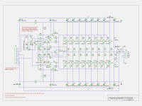
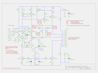
Updated schematics ...
attached updated schematics.
Feel free to use for non commercial DIY projects.
BR, Toni
attached updated schematics.
Feel free to use for non commercial DIY projects.
BR, Toni
Attachments
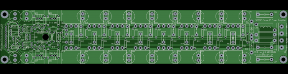
Updated bias output stage pcb
attached updated pcb for bias and output stage.
Feel free to use for non commercial DIY projects.
NOTE: this PCB version is currently untested. I have uploaded it for those who can't wait. You have been warned!
The amplifier is tested using output stage pcb rev 1.0 but using cap, transistor and resistor values from schematic from post #671.
BR, Toni
Attachments
My pcb software doesn't make thermals very well so I have decided to omit them as I do not have any problems with soldering (of course your solder iron should be temperature controlled with > 80W heating).I don't see it well, but I think you are missing the thermal spokes in the pads embedded in your planes. Having those makes soldering a lot easier.
BR, Toni
I had the chance to listen to the finished amp for several hours. It was no surprise to me that you have created a very well sounding amplifier. Excellent work! Congratulations, Toni!
Thanks! Give me some time and we can hear the bi-amping variant using active crossover...
- Home
- Amplifiers
- Solid State
- 2stageEF high performance class AB power amp / 200W8R / 400W4R