* SA2022 - Modular High End Precision Preamplifier * See Project J below ***
* SA2021-NCH - New Class H * SA2021-NCH - New Class H * See Project I below *
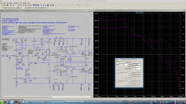
Heavily inspired from books of Douglas Self, Bob Cordell and other great authors I decided to design a discrete power amplifier to learn how LTSpice can be used for my DIY projects.
Attached is the current simulation file and some information about the real world result: a very good working 2stageEF power amplifier with high performance.
The simulated THD performance is about 0.0004% at 20kHz@200W@8R.
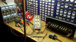
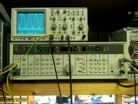
Real life THD+N performance of working prototype amplifier is about 0.0015% at 20kHz@200W@8R (80kHz bandwidth).
Using the HP3585A spectrum analyser (100dB resolution) while running 20kHz@200W@8R test only H2 and H3 are visible above the noise floor.
To download the needed BJT/JFET/MOSFET/DIODE ltspice library file "Cordell-Models.txt" please visit CordellAudio.com - Home
During the years some smaller amplifiers based on the same topology have been developed. These projects have been discussed in detail and have been built successfully by different users. See the index below for more information.
In addition a high performance discrete opamp "MyDOA" and housekeeping circuits have been developed and built many times too.
More test results, THD plots and other information will be updated from time to time.
Have fun, Toni
-----------------------------------------
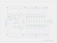
A) SA2014 (200W@8R, 400W@4R) Rev 3.4.2 amplifier (partially old name is SA2013) using 8 matched pairs TTC5200 and TTA1943:
- Latest valid PCB gerber files for input/VAS and output stage board can be found in post 979 and 980
- PCB gerber files for power supply (single diode bridge; v3.x; see F) and G) below for dual diode bridge) for one channel in post 1005
- Latest schematic and corrected BOM in post 1145 and 1146
- R28 (100R) needs to be reduced to 68R to get some extra PM stability.
- CCS mod for better thermal stability post 2028
- "asc" files can be found in post 1149
- pcb's are available via: sa2014 (at) aws-it.at
- post #1255: MyDOA v3.1 final - schematic and gerber files
- MyDOA measurements
- pcb's are available via: mydoa (at) aws-it.at
- post #1409: SA2015 final schematic, bom, gerber files - rev 1.3
- pcb's are available via: sa2015 (at) aws-it.at
- post #2185: SA2015 IXYS schematic ("product id": SA2017-VMOS-AB4-800)
- pcb's are available via: sa2015 (at) aws-it.at
- Schematic and BOM part 1 is here
- Schematic and BOM part 2 is here
- pcb's and PIC microcontroller firmware are available via: sa20xx-hk (at) aws-it.at
- preliminary schematic for ECX10N20, ECX10P20 can be found in post 1761
- pcb's are available via: sa2016 (at) aws-it.at
- preliminary schematic for double die ECW20N20 and ECW20P20 can be found in post 2105
- pcb's are available via: sa2016 (at) aws-it.at
- schematic for dual diode bridge ("big" sized: 150x150mm) can be found in post 2000 and 2001
- updated gerber files in post 2067, 2068
- pcb's are available via: sa2014 (at) aws-it.at
- schematic for dual diode bridge (smaller size: 150x90mm) can be found in post 1987 and 1988
- updated gerber files in post 2067, 2068
- images of working test samples in post 2071
- pcb's are available via: sa2016 (at) aws-it.at
I) SA2021-NCH - a 'New Class H' prototype using 3 matched pairs IXYS IXTH80N20L/IXTH48P20P and 4 matched pairs TTC5200/TTA1943
- single pair IXYS prototype schematic can be found here post 2902
- single pair IXYS working prototype can be found here post 2922
- 3 pair IXYS - v2.0 preliminary schematic - can be found here post 3117
- 3 pair IXYS powered amplifier testing can be found here and on the following posts: post 3094
- SA20XX Amplifiers need a preamplifier - this project may fullfill your needs: post 1
INDEX / UPDATES
- 2013.05.10: Just4Fun: simulation of OPS using discrete darlingtons
- 2013.05.10: Just4Fun: simulation with MOSFET IRFP240/IRFP9240
- 2013.06.16: New schematics for revision 2.0RC1 available here
- 2013.06.21: THD performance of Rev2.0RC1: THD20k@200W@8R with distortion magnifier and VP-7723D 0.00152 % (bw. 80kHz) 0.00184 % (no bw. limit)
- 2013.06.29: Milestone SA2013-Rev2-RC1: All pcb's ready for mounting and cabling
- 2013.07.24: Prototype finished. Ready for extended hearing tests ...
- 2013.07.28: THD Performance of finished amplifier
- 2013.07.29: Updated schematics for revision 2.0 available here
- 2013.07.31: Updated PCB for input/vas and bias/output stage rev. 2.0
- 2013.10.13: Just4Fun - a symmetrical input/VAS variant
- 2013.10.14: The effect of too less gain margin
- 2013.10.17: Just4Fun: 2stageEF as current feedback amplifier variant
- 2013.10.20: Just4Fun: my discrete opamp V2 / my_doa_v2
- 2013.10.27: Just4Fun: my discrete opamp V3 / my_doa_v3
- 2013.12.29: Updated schematics/ltspice-file for revision 2.2 available here. Fix VAS current protection
- 2013.12.30: Milestone SA2013-Rev3-Alpha: new VAS topology improves THD
- 2013.12.31: New VAS topology real life measurements
- 2014.01.13: VAS current protection redesign: avoid overload / ringing
- 2014.01.13: VAS current protection redesign: better sticking behaviour
- 2014.02.16: The effect of current mirror degeneration on slew rate
- 2014.04.27: Distortion and overload tests - SA2013 v3.1
- 2014.05.03: IMD measurements - SA2013 v3.1
- 2014.05.03: Noise - SA2013 v3.1
- 2014.05.29: SA2013 v3.4 THD measurements
- 2014.05.30: SA2013 v3.4 IMD measurements
- 2014.05.30: SA2013 v3.4 Noise measurements
- 2014.05.31: Just4Fun: simulation with MOSFET VAS IRF9610
- 2014.06.09: Real life test results MOSFET VAS IRF9610
- 2014.06.22: Input/VAS/OPS schematics and pcb for revision 3.4.0 final
- 2014.06.26: Powersupply schematics and pcb revision 3.4.0 final
- 2014.06.28: Powersupply simulation for CRC snubber
- 2014.06.28: Powersupply schematics and pcb revision 3.4.1 (with added RC snubber)
- 2014.09.14: Revision 3.4.2: Final schematics and BOM
- 2014.11.29: Fighting the hum - encapsulating power supply using soft iron
- 2015.03.03: Playing with LTSpice - dual Tian probe and parameter stepping
- 2015.02.10: MyDOA v3.1 final - schematic and gerber files
- 2015.09.18: SA2015 with V-MOSFETs IRFP240/IRFP9240 - is born. A high performance 75W@8R, 150W@4R MOSFET amplifier
- 2015.09.19: SA2015 with V-MOSFETs IRFP240/IRFP9240 - measurements THD20k@50W@8R 0.0018%
- 2015.10.31: SA2015 with V-MOSFETs IRFP240/IRFP9240 - final schematic, bom, gerber files - rev 1.3
- 2016.03.16: SA2013, SA2014, SA2015 housekeeping circuits
- 2016.04.10: SA2015 with V-MOSFETs IRFP240/IRFP9240 - first powering procedure after assembling
- 2016.07.07: SA2015 with V-MOSFETs IRFP240/IRFP9240 - pictures of the finished 4 channel amplifier
- 2016.07.15: Housekeeping Circuits V4.3 - schematic and bom - part 1
- 2016.07.16: Housekeeping Circuits V4.3 - schematic and bom - part 2
- 2016.08.05: SA2016 with L-MOSFETs EXC10N20 EXC10P20 - measurements 1 - noise
- 2016.08.10: SA2016 with L-MOSFETs EXC10N20 EXC10P20 - measurements 2 - noise / THD table
- 2016.08.10: SA2016 with L-MOSFETs EXC10N20 EXC10P20 - using higher rail voltages to get 115W @ 8R
- 2017.01.31: pcb clearance, creepage discussions 1: EN 60950-1
- 2017.02.01: pcb clearance, creepage discussions 2: EN 62368
- 2017.02.05: SA2014 input stage reloaded: small mod of the CCSs for better thermal stability
- 2017.02.09: SA2014 heatsink thermal simulation with LTSpice
- 2017.02.20: New SA2014/SA2015/SA2016 power supply variants are working
- 2017.02.20: Off topic: Linkwitz-Riley 24dB subwoofer analog crossover - 2.1 system
- 2016.02.26: SA2016 with L-MOSFETs double die ECW20N20 ECW20P20 - singing - THD20k+N@200W@8R 0.0052%, THD20k+N@320W@4R 0.008%
- 2017.03.05: SA2015 with IXYS V-MOSFETs IXTH80N20L and IXTH48P20P - SOA simulation
- 2017.03.12: SA2015 with IXYS V-MOSFETs IXTH80N20L and IXTH48P20P - first powering
- 2017.03.13: SA2015 with IXYS V-MOSFETs IXTH80N20L and IXTH48P20P - measurements - THD20k+N@60W@8R 0.0018% (80k bw)
- 2017.03.16: SA2015 with IXYS V-MOSFETs IXTH80N20L and IXTH48P20P - schematic
- 2018.11.11: SA2015 with IXYS V-MOSFETs IXTH80N20L and IXTH48P20P - finished 4 channel amplifier ("product id": SA2017-VMOS-AB4-800)
- 2020.10.29: DaveZan presents a draft for a switch mode rail tracker class H design
- 2020.11.20: SA2021-NCH 'New Class H' by DaveZan and ASTX - prototype using IXYS V-MOSFETs and TTC5200/TTA1943 - lab test schematic
- 2021.01.05: SA2021-NCH 'New Class H' by DaveZan and ASTX - prototype working - excellent low distortions as expected
- 2021.01.05: SA2021-NCH 'New Class H' - prototypes first THD and noise measurements at 200WR
- 2023.07.22: SA2021-NCH 'New Class H' - assembling the 3 pair IXYS MOSFET powered amplifier
- 2023.07.25: SA2021-NCH 'New Class H' - assembling / preliminary schematic of 3 pair IXYS powerhorse
- 2023.07.31: SA2021-NCH 'New Class H' - first powering and measurements
- 2016.04.11: Thimios build SA2015 - first power on, many tests on following posts
- 2016.04.12: Thimios build SA2015 - testing first sample
- 2016.04.15: Thimios build SA2015 - second channel
- 2016.05.19: Thimios build SA2015 - ready for hearing tests
- 2017.05.18: Thimios opened build thread: SA2015-V-MOSFET-Builders
- 2016.04.12: SGK build SA2014 - assembled!
- 2016.08.18: SGK build SA2014 - from build start to singing at post 1831
- 2017.01.05: SGK build SA2014 - internal view
- 2017.01.05: SGK build SA2014 - SMD variant of housekeeping pcb
- 2017.01.07: SGK build SA2014 - finished, front view
- 2017.02.19: SGK build SA2014 - panel switch pcb 1
- 2017.02.20: SGK build SA2014 - panel switch pcb 2
- 2017.03.12: SGK build SA2014 - Alternative auxiliary power supply
- 2017.03.13: SGK build SA2014 - Main power supply
- 2018.01.25: SGK build another SA2014 - now as monoblock
- 2016.11.22: AndrewT (R.I.P) build SA2016 - up and running using double die Exicons
- 2017.11.19: HYPERTUNE opened build thread: ASTX SA2014 Build Thread. 2 x 400WR with CNC machined case.
NOTE: the pictures and schematics shown in this first post are from the initial beta project. Do NOT use them for production. Read above index carefully - there are links to the latest schematics, BOM and gerbers!
Attachments
-
 2ef_simulation.png207.2 KB · Views: 25,670
 -
 SA2013_high_power_stability_test.jpg277.9 KB · Views: 9,525
 -
 SA2013_discrete_class_ab_output_stage_schematic.png178.2 KB · Views: 24,577
 -
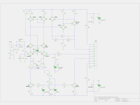 SA2013_discrete_class_ab_input_vas_stage_schematic.png191.8 KB · Views: 25,148
 -
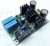
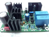
 SA2013_assembled_2.jpg326.5 KB · Views: 24,072
 -
 SA2013_assembled_1.jpg250.8 KB · Views: 24,437
 -
2stageEF_class_AB_power_amplifier.asc37.3 KB · Views: 1,495
-
ltspice_libs.zip1.3 KB · Views: 1,074
-
 SA2013_THD_20kHz_200W_8R.jpg151.6 KB · Views: 4,877
Last edited:
Using 2N5401 for Q1 and Q2 is a mistake. At low Vce these transistors perform badly.
The BC5x0, BC3x7, and 2SA1015 are known to have excellent okay quasi-sat behavior. There are virtually no transistors with Vcemax>50V that have good quasisat behavior.
Because SPICE does not model quasi-saturation, this problem will not show up in your simulations. However, since the above recommended transistors are pretty close to ideal, if you use Cordell's or NXP (Phillips) models for them they will get you within 6db of real life at low Vce.
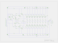
... think you are referring to ltspice simulation file as the part numbering of the attached schematic pictures is different:
Maybe you are right that 2N5401 is not the best BJT for the current mirror.
Using BC560C instead of reduces THD simulation indeed about 3ppm.
BTW the used transistors for Q1/Q2 are hand selected from a big number of measured devices and have hfe > 220. Perhaps this is the reason, that the real world amplifier THD figure is better as simulated one...
Will try your BJT tipps the next days in real world.
Thx,
Toni
In your setup matching the CM transistors isn't going to do anything if the CM degeneration isn't also matched. I posted about it here:
http://www.diyaudio.com/forums/solid-state/192431-diyab-amp-honey-badger-19.html#post3312987
http://www.diyaudio.com/forums/solid-state/192431-diyab-amp-honey-badger-19.html#post3312987
Q1/Q2 CM matching data ...
Your explanation is very interesting.
Q1 and Q2 matching data:
Left channel:
BJT#30: hfe=224 vbe=-0.5670
BJT#173: hfe=224 vbe=-0.5660
Right channel:
BJT#35: hfe=230 vbe=-0.5670
BJT#128 : hfe=230 vbe=-0.5660
100R resistors are matched < 0.5% tolerance.
So what would be your choice for Q1/Q2 CM and degeneration (2.2mA per leg)? (Amp is using nominally +/- 66V and max. +/- 72V power supply)
BR,
Toni
I go by Slone's advice to degenerate by 50mV. 50mV / 2.2mA =~ 22R. Degeneration is specified as voltage drop because Gm is proportional to Iq and so is the degeneration voltage drop. This way degeneration can be described conveniently independent of Iq.
I would use BC560C in the CM because they are very fast, have high gain, and have good enough Vcesat. For a CM, I think they are as close to ideal as you can get.
I would use BC560C in the CM because they are very fast, have high gain, and have good enough Vcesat. For a CM, I think they are as close to ideal as you can get.
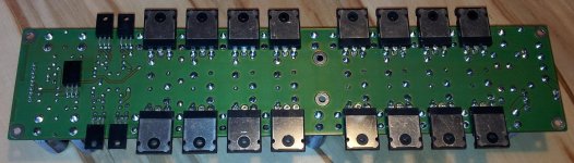
PCB and input stage assembling details ...
Before soldering the heat sinks place pvc washers between pcb and heatsink solder legs to avoid short circuit with rail voltages. Do this even if your pcb has a very good stop paint!
Before soldering the heat sinks place pvc washers between pcb and heatsink solder legs to avoid short circuit with rail voltages. Do this even if your pcb has a very good stop paint!
Attachments
I have been using 200mV to 300mV as the Vdrop of the degeneration resistor, in LTP, & VAS & Current Mirror.I go by Slone's advice to degenerate by 50mV. 50mV / 2.2mA =~ 22R. Degeneration is specified as voltage drop because Gm is proportional to Iq and so is the degeneration voltage drop. This way degeneration can be described conveniently independent of Iq...............
What is wrong with doing it that way? excess added noise? or many other avoidable problems?
Member
Joined 2009
Paid Member
I have been using 200mV to 300mV as the Vdrop of the degeneration resistor, in LTP, & VAS & Current Mirror.
What is wrong with doing it that way? excess added noise? or many other avoidable problems?
If you refer back to my post I linked to earlier, a lot of degeneration really isn't necessary and isn't really helpful unless your degeneration is matched, and even then it's questionable. LTPs benefit from matching but not THAT much, especially if the rest of your circuit produces significant H2. If you really want that level of matching, you will not get it by obsessing over matching; you should use trimmers instead.
Furthermore, large degeneration bootstraps Cbe and can slow down the transistor. The BC5x0C have reasonably small Cbe, but not the 2N5401's that people always try to use here.
I think a distinction could be made between common-mode degeneration and differential-mode degeneration. LTP degeneration is differential. CM degeneration is common. The difference is that LTP degeneration will influence harmonic profile while nominally, CM degeneration will not.
Different purposes can require different standards of degeneration. Slone chose the 50mV figure specifically for current mirrors, because is it large enough to swamp the differences in BJTs, but not larger than it needs to be.
For other degenerations, such as an EF output stage or an LTP, the needs are different. For an EF, there is the Oliver null point, above or below which you get more Gm distortion. For LTPs, it's usually a question of stability and slew rate. Degeneration also changes the harmonic profile, and I've heard 200mV is preferred by some designers in places where it affects the sound.
For a sense of scale, BJTs tend to have an emitter impedance of .026/Iq. So if we set degeneration to 26mV, our resistor matches the emitter impedance. At 200mV, the resistor is 6 times the emitter impedance. Whether degeneration is above or below 26mV determines whether the stage's Gm is mostly logarithmic or linear.
Last edited:
I have been using 200mV to 300mV as the Vdrop of the degeneration resistor, in LTP, & VAS & Current Mirror.
What is wrong with doing it that way? excess added noise? or many other avoidable problems?
In contrast noise will be much reduced in the LTP which is good, one shouldnt use low degeneration as Self or Slone suggest. Larger degeneration will lower the gain a little but in terms of THD you might be looking at 1ppm for a change from 22R to 220R. Noise can be lowered by as much as 15db. The lowering of the gain is also good as all current mirrors show some peaking in their response and this atenuates it.
Noise is the parameter most affected by degeneration. In most IC opamp design literature youll find references to this. Its true though that other mirrors have much higher peaking. Usually one should include a small capacitance accross the BE junction of the helper transistors to tame the peaking although using higher degeneration is enough for the basic mirror. So having high Cbe is not always such a bad thing.
Just thought of a good reference :Analogue Ic Design: The Current-Mode Approach by Christofer Toumazou, F. John Lidgey, David G.. Haigh.
Just thought of a good reference :Analogue Ic Design: The Current-Mode Approach by Christofer Toumazou, F. John Lidgey, David G.. Haigh.
slobber slobberCongratulations on this beautiful piece of engineering.
It looks looks really professional to me - you must do this for work too and not just as a DIY hobby!
Thanks for sharing this btw - really very inspiring stuff
Thank you. I am very happy to have such a beautiful hobby.
Don't forget to visit this thread from time to time!
BR,
Toni
Wow, looks good, you have a nice bench set up there and you've built a good looking amplifier. I hope you are pleased with the sound too.
Thank you. It measures very good and it sounds very good in mono (the second/other channel is assembled and mounted on heatsink since yesterday, but not yet ready for listening - needs the burn in test 1 hour full load 20kHz@200W8R).
BR,
Toni
Dear keantoken, manso, AndrewT
interesting discussion about current mirrors. During learning LTSPice I have simulated "simple current mirror", "EFA current mirror", "wilson current mirror" and "4 transistor improved current mirror". Douglas Self has made a comparison between these 4 CM types (APAD Handbook, Fifth Edition, page 85) .
One of the conclusion I made, that if using bjt's with beta > 200 the error of the simple current mirror between current in/out is very low in comparison to the "better CM" variants. So I decided to use a simple current mirror as the simulation showed only a few ppm THD difference.
As there are many empty input stage pcb's left (got it cheap from overproduction) I will try to test different bjt's and degeneration values during the next days and will give a feedback
Btw.: the same input/vas stage exists assembled with matched 2SK170 and about 150R degeneration. Will add ltspice asc file the next days.
Note: one can never have enough good amplifiers!
BR,
Toni
interesting discussion about current mirrors. During learning LTSPice I have simulated "simple current mirror", "EFA current mirror", "wilson current mirror" and "4 transistor improved current mirror". Douglas Self has made a comparison between these 4 CM types (APAD Handbook, Fifth Edition, page 85) .
One of the conclusion I made, that if using bjt's with beta > 200 the error of the simple current mirror between current in/out is very low in comparison to the "better CM" variants. So I decided to use a simple current mirror as the simulation showed only a few ppm THD difference.
As there are many empty input stage pcb's left (got it cheap from overproduction) I will try to test different bjt's and degeneration values during the next days and will give a feedback
- if 2N5401 is really a mistake in this case or
- more or less degeneration will improve or worsen distortion measurements
- produces more or less harmonics. (currently only H2 and H3 are visible above 100dB / measurement noise floor of HP3585A)
Btw.: the same input/vas stage exists assembled with matched 2SK170 and about 150R degeneration. Will add ltspice asc file the next days.
Note: one can never have enough good amplifiers!
BR,
Toni
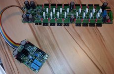
I feel truly honored to be a frequent visitor and guest in the Astx Lab. Toni is the tech-guru of our DIY group. He learns and develops his stuff at an extraordinary fast pace. I cannot think of someone to keep up... So my guess: We do not have to wait long for the finished result I like that he did a discrete amp this time. The board layout is very nice!
BTW, I am in the process of building a 4-channel amp on Toni's schematics and boards. That one is based on the LME 49830 and I am going to start a thread about that build in the chip amps section when the amp is finished.
Cheers, Martin
I like that he did a discrete amp this time. The board layout is very nice! BTW, I am in the process of building a 4-channel amp on Toni's schematics and boards. That one is based on the LME 49830 and I am going to start a thread about that build in the chip amps section when the amp is finished.
Cheers, Martin
I feel truly honored to be a frequent visitor and guest in the Astx Lab.
...
Many thx martin! Going to buy extra beer for our next lab meeting...
BR,
Toni
- Home
- Amplifiers
- Solid State
- 2stageEF high performance class AB power amp / 200W8R / 400W4R