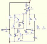
Look at that. The circuit is more complementary than a conventional. Both legs have the same transistors -- both NPN and PNP.
Super complementary output
So in theory the gain of top and bottom is the same... plus it is two times higher than in a conventional Darlington. But will it work in reality?
Super complementary output
So in theory the gain of top and bottom is the same... plus it is two times higher than in a conventional Darlington. But will it work in reality?
Looks like bryston type output. Check schematic on page 6 of 2b manual http://www.bryston.com/PDF/Manuals/2B_MANUAL.pdf .
This is a much clearer example try here: http://www.bryston.com/PDF/Schematics/3B-8BST_SCHEMATICS.pdf
And there are a few others who use similar topology..
And there are a few others who use similar topology..
This is a much clearer example try here: http://www.bryston.com/PDF/Schematics/3B-8BST_SCHEMATICS.pdf
And there are a few others who use similar topology..
Thanks. So this topology can work in practice.
but here is a real gem, on the bottom of the page, fig 6: Low distortion follower
from the description it is working circuit.
from the description it is working circuit.
Thanks. So this topology can work in practice.
hahaha yes

Look to my signature SSA link below, from year 2000 using BIGBTs

hahaha yes
Look to my signature SSA link below, from year 2000 using BIGBTs
ESL5012 looks like a decent amplifier using this super-complementary output. But in reality, will the "super-complementary" follower work better than a conventional Darlindton or Sziklai? Is it any better than paralleling the same polarity per each leg transistors (with current sharing emitter resistors)?
My understanding is that for a deep-feedback design super-complementary stage does not give marked advantage. Not sure about crossover distortion. It is possible that N and P siblings in the same leg will not go into cut-off at the same time. So the switchover between top and bottom sides might be more "smeared". Whether it is good or bad -- I do not know.
I thought about converting a quasi output stage to a "Bryston" style stage by adding a pair of transistors.
Until a Member pointed out that cross conduction may be a very big problem.
Bryston's designers could probably design out of the hole they dug, but I was not confident I had the skills to do likewise.
Until a Member pointed out that cross conduction may be a very big problem.
Bryston's designers could probably design out of the hole they dug, but I was not confident I had the skills to do likewise.
Hello AndrewT. JLH comes to mind.I thought about converting a quasi output stage to a "Bryston" style stage by adding a pair of transistors.
Until a Member pointed out that cross conduction may be a very big problem.
Bryston's designers could probably design out of the hole they dug, but I was not confident I had the skills to do likewise.
ESL5012 looks like a decent amplifier using this super-complementary output. But in reality, will the "super-complementary" follower work better than a conventional Darlindton or Sziklai? Is it any better than paralleling the same polarity per each leg transistors (with current sharing emitter resistors)?
My understanding is that for a deep-feedback design super-complementary stage does not give marked advantage. Not sure about crossover distortion. It is possible that N and P siblings in the same leg will not go into cut-off at the same time. So the switchover between top and bottom sides might be more "smeared". Whether it is good or bad -- I do not know.
Youre right its not better, in fact its worse. When you study it youll notice that especially 3 rd and odd order harmonics are worsened which suggests that cross-over is worsened. It was however novel and as the odd order harmonics tend to make the sound brighter than it should be many falsly believe the stage to be superior.
The more enlightened and not easily fooled will stick to conventional darlington.
hi
I started to be suspicious about this follower
I even cannot set it up right in ltspice
Hi Pawel, I think the problem is that 2N5462 does not emulate J177 -- cutoff voltage of the later is much higher.
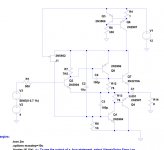
I suggest remove this "crap": R8, C4, J1. (Numbering according to your emulated schematic, not according to the original.) Instead just fit a 9.1V Zener across source-drain of where J1 used to be. Also connect say 2.2K resistor across base-emitter of Q3, to give the Zener some bias current.
Thus voltage across both legs of the follower will be maintaned at 9.1V + 0.6V = 9.7V, leaving about 2.3V for the top current source -- should work... I guess... fingers crossed.
thank you for the suggestions
but still not working
I installed LTSpice (though have never used simulators before) and tested this circuit using the relatively low power transistors from the default library (they will not burn out on the simulator).
Also connected the gate of the JFET 2N5462 (from the library) directly to +12V to account for its higher cut-off.
Instead of input voltage divider used just a bias DC voltage of 4V.
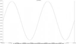
Used 0.7Vm input, 1kHz and 8R load.
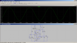
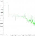
Works fine! FFT plot gives -90dB on the output with some strange hairy aliasing on HF above 100kHz. But on the input the FFT plot is the same. So on the simulator the distortion is "unmeasurable" -- can not tell the difference between input and output.
I have played with the LTSpice for an hour or so, and have not learned how to tune/customize the FFT yet. I derived everything from one of their demo circuits.
Conclusion -- the circuit rather works than not and possibly is very good for the earphones.
works?
before ltspice I used b2spice (J. Broskie, Beigebag, TubeCad Journal).
there is easier changing models in ltspice, than in b2spice,
maybe you will find it friendly too?
I was thinking about this circuit to be working with computer psu +12 which I have lots.
For headphones it is oversized/overpowered...
CFP is not easy to calm from the oscillations...
... it is not yet grinded gem maybe...
I was thinking about this circuit to be working with computer psu +12 which I have lots.
For headphones it is oversized/overpowered...
CFP is not easy to calm from the oscillations...
... it is not yet grinded gem maybe...
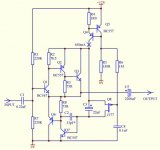
Well, the original circuit comes from here. It is in the first thumbnail below.
What I actually simulated is shown in the second thumbnail. I added a compensation cap to minimize ringing on step transient. I changed the JFET and had to rewire it, as the original low-cutoff one, J177, was not in the library. The circuit sort of "works", but I do not trust this FFT. In the attachment the output FFT is shown. But the input looks very similar. So it is impossible to see how much distortion is added by the follower. It is probably very low, but again who can trust a simulator? I am sure it does not take into account temperature oscillation of the transistor dies.
I am a novice to the simulator and have not mastered it. Always have been working with a soldering iron.
If the amplifier looks overpowered, you can always reduce bias current by increasing current source setting resistor R4. Also I think you can cut down the compound follower replacing the three-stage compound follower just by a Sziklai or Darlington. Will be more stable... perhaps.
Regards,
Alex
Attachments
- Status
- This old topic is closed. If you want to reopen this topic, contact a moderator using the "Report Post" button.
- Home
- Amplifiers
- Solid State
- Super-complementary output stage