Hi jxdking,
What do you mean by performance? Is it just the final result or do you think that we can have a relevant feedback path in the circuit with second-order characteristics, while the overall behaviour is first-order?
Here is what I was talking about. Please see the attachment.
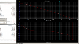
2-Pole performance
1-Pole like frequency response.
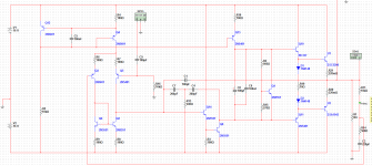
C1 is the outer Miller Capacitor.
Actually, you must come up 2 or more pole at inner loop, so that you can have some extra gain (at lower frequency) for outer loop to do the compensation.
Attachments
Dear jxdking,Here is what I was talking about. Please see the attachment.
2-Pole performance
1-Pole like frequency response.
C1 is the outer Miller Capacitor.
thank you for reasoning and sharing your results. Maybe, I first have to better clarify the main idea proposed in this thread.
With the advent of low-voltage OPA, especially CMOS, IC designers had the problem that the active devices did not provide enough transconductance in order to get good DC gain figures. This was due to the standard OPA architecture with only two effective gain stages: differential transconductance plus transimpedance stage (VAS). Thus, they were forced to throw in more gain stages that had to be compensated somehow. Nested Miller compensation is in my eyes just the simplest scheme, more are discussed e.g. in Johan Huijsing's book. (BTW, also thrilling there: biasing circuits for rail-to-rail A/B output stages [without cut-off], linearisation of rail-to-rail input stages, multipath frequency compensation and discussion of many design examples, including a few important standard OPA)
Lacking DC gain is of course not our problem. But each nested Miller compensation loop does provide, as a side-effect, extra feedback around the output stage. This is what I'm proposing to exploit.
Looking at your schematic, I'm not sure whether the feedback via C1 will work as intended. If I get it right, you first set the VAS gain by the two-pole compensation network with C4 and C7. Then you apply a loop around this stage and OPS via C1. I'm wondering whether this will work as intended, if you do not isolate the two "left-hand sides" of feedback networks. They both are connected to the VAS input and will interfere somehow. Additionally, there is no voltage gain between the "right hand sides" of both networks. In my examples, both "left-hand sides" are isolated by a transconductance stage in between which will provide additional gain. Did you probe the loop gains of both loops?
Cheers,
Matze
Hi David,
thanks for your comments.
Best regards,
Matze
thanks for your comments.
Unfortunately, I do not get your point. Do you think that one has to tackle all nested loops at once? My hope was that one can decompose the problem. Then, in each loop on its own, only the pole created by the ULGF of the next inner loop had to be cancelled. Even if that's not exactly possible, the phase margin penalty due to a pole-zero pair just at the ULGF seems to be small, see simulation results.I think one problem with your derivation is that there is an implicit assumption of perfect minimum phase. If phase behaviour is perfectly minimum then every pole but one can be perfectly canceled and the result will be first order behaviour.
This is also the assumption behind Cherry's Nested Dif. Feedback Loops.
The hope is still that, using nested loops, the maximum relevant ULGF in the whole circuit can be kept low (and what I see in practice from my breadboard amplifier with its ridiculous number of nested loops, it seems to be the case ...). If one used one loop instead and tried to cancel all disturbing poles therein, then still the relevant ULGF would remain high, if large total amounts of NFB were to be generated with first-order behaviour.If you can do this then do you need nested loops? Just cancel the poles and have a first order loop.
This kind of hidden assumption can be quite tricky.
Best regards,
Matze
The hope is still that, using nested loops, the maximum relevant ULGF in the whole circuit can be kept low (and what I see in practice from my breadboard amplifier with its ridiculous number of nested loops, it seems to be the case ...).
I probably should have asked this at the start to clarify what to discuss.
Have read Cherry's articles on Nested Diff. Feedback Loops?
There are several in ETI and at least one in JAES.
Have you read JCX's posts on TMC?
These disprove claims similar to your proposition. I think the extra return ratio may not be evident in the outer loop but it will exist in some loop and will have consequences on the phase of that loop and the overall behaviour of the amp.
The ULGF can be kept low but the phase below that frequency must reflect the increased rate that the return ratio declines.
Thanks for the mental work-out
")
Best wishes
David.
Dear jxdking,
Looking at your schematic, I'm not sure whether the feedback via C1 will work as intended. If I get it right, you first set the VAS gain by the two-pole compensation network with C4 and C7. Then you apply a loop around this stage and OPS via C1. I'm wondering whether this will work as intended, if you do not isolate the two "left-hand sides" of feedback networks. They both are connected to the VAS input and will interfere somehow. Additionally, there is no voltage gain between the "right hand sides" of both networks. In my examples, both "left-hand sides" are isolated by a transconductance stage in between which will provide additional gain. Did you probe the loop gains of both loops?
Actually, C1 could be any value, as the maximum ULGF is restricted by 2 pole compensation. It will be stable anyway. At very high frequency, the equivalent Miller Cap value will be (C1+(C4//C7)).
C1 is intended to do Miller Compensation including output stage. That's our goal, isn't it?
1. The tricky part is what the 2 pole compensation is doing here. Why has to be 2 pole configuration. In order to keep output stage stable, the ULGF should be restricted even if C1 is not added. Thus, you have 2 choice.
(1) one choice is traditional miller compensation for inner loop. In this case, it makes outer Miller Cap useless but lower the ULGF.
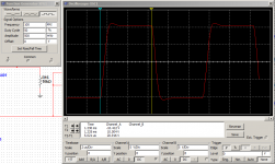
(2) another choice is 2 pole compensation for inner loop. 2 pole will be 40dB/Oct rolling down, you will get a big hump at low frequency response. At low frequency, you will have lots of extra gain comparing to 1 pole. Thus, you can use outer loop to Compensate the extra gain. C1 will dominate at low frequency. The overall frequency response will look just like 1 pole.
2. You mentioned using extra stage. Yes, you can do that, but it will be more complicated. Here is my rule. The whole amplifier should be stable even if removing all the outer Miller Caps, because the most inner loop should be dominant at high frequency to make sure everything is stable. It will be pretty tricky to achieve that rule with extra stage.
3. After playing around simulation for a while, I find the THD performance is pretty equivalent to TMC compensation. Actually, it should be. The beautiful part is that they can work together. Should I call it Nested Transitional Two Pole Compensation?

Last edited:
Hi David,
thanks again for your comments. I will try to do my homework; the Cherry paper left the printer.
Best regards,
Matze
thanks again for your comments. I will try to do my homework; the Cherry paper left the printer.
You are right. It's time to pause a bit. But I fear I will come back and make noise with my spoons.Thanks for the mental work-out
Best regards,
Matze
Hi jxdking,2. You mentioned using extra stage. Yes, you can do that, but it will be more complicated. Here is my rule. The whole amplifier should be stable even if removing all the outer Miller Caps, because the most inner loop should be dominant at high frequency to make sure everything is stable. It will be pretty tricky to achieve that rule with extra stage.
3. After playing around simulation for a while, I find the THD performance is pretty equivalent to TMC compensation. Actually, it should be. The beautiful part is that they can work together. Should I call it Nested Transitional Two Pole Compensation?
the whole idea is really about adding new gain stages. This allows to obtain excellent performance without ULGFs in the MHz region. TMC does promise a THD20 improvment of, say , factor 5. Extra transconductance stages with nested Miller compensation can provide improvments of orders of magnitude, see the examples with Bob's amplifiers in earlier posts. In this respect, the undertaking is more comparable to OPS error correction approaches with the difference that no trimming would be necessary.
My goal is to use rather slow, but stable and rugged output stages as well as low ULGF in all feedback loops of the topology. Considering the available devices and e.g. the surprisingly simple, yet really high-performance approach of Dadod's TT-TMC, this may seem a bit strange. But the point is more in exploring the applicability of principles that are routinely used in other areas of analog design, but not yet appreciated in audio amplifier construction.
Cheers,
Matze
slow, rugged seems like a handicap - why not fast rugged?
or improving less rugged, fast devices with paralleling
fast is really helpful in allowing stable use of more gain in the working band - more "distance" in frequency to "unwind" the excess phase
Bode only gave preliminary hints for properly measuring multiloop systems
I think the simple view is if you can cut the amp signal path in a spot that cuts all of the loops, and everything relies only on individually stable negative feedback - then you have a chance to see the stability in a single loop gain plot
I try not to miss any chances to recommend BJ Lurie's work - although his books are hard to understand and "buggy" - needing 2nd editions but he really shows how to use Classical Control techniques - you can still view his old site with archive.org
Dr. Boris J. Lurie's Homepage: Classical Feedback Control
looks like there is now a 2nd edition
one thing Lurie does really well is show that the “conservation” relation for the total amount of feedback - the “Bode Integral” is exactly such a practical "good theory" - and has been the underpinning fundamental argument behind my posts in this thread
http://trs-new.jpl.nasa.gov/dspace/bitstream/2014/19495/1/98-0905.pdf
of course the real bottom line is that audibly "transparent" amps are trivial - especially if spending a few 10s of W heavy Class AB bias is possible
I like control theory, electronic design - electronic power amplifcation just isn't where the limitations in audio reproduction are - its in speakers and room
Last edited:
slow, rugged seems like a handicap - why not fast rugged?
or improving less rugged, fast devices with paralleling
fast is really helpful in allowing stable use of more gain in the working band - more "distance" in frequency to "unwind" the excess phase
Bode only gave preliminary hints for properly measuring multiloop systems
I think the simple view is if you can cut the amp signal path in a spot that cuts all of the loops, and everything relies only on individually stable negative feedback - then you have a chance to see the stability in a single loop gain plot
I try not to miss any chances to recommend BJ Lurie's work - although his books are hard to understand and "buggy" - needing 2nd editions but he really shows how to use Classical Control techniques - you can still view his old site with archive.org
Dr. Boris J. Lurie's Homepage: Classical Feedback Control
looks like there is now a 2nd edition
one thing Lurie does really well is show that the “conservation” relation for the total amount of feedback - the “Bode Integral” is exactly such a practical "good theory" - and has been the underpinning fundamental argument behind my posts in this thread
http://trs-new.jpl.nasa.gov/dspace/bitstream/2014/19495/1/98-0905.pdf
How fast is fast? 1MHz ULGF?
Most books tell me 500KHz ~ 800KHz is the safety region. Actually, I have never thought about it before. I just reference others experience. You give me a good question.
I think Bob's MOSFET amp, measured inside the error corection loop manages ~4-5 MHz
http://www.diyaudio.com/forums/soli...terview-error-correction-250.html#post1328496
probably RET bipolars can do nearly the same, somewhere not much higher standard packaging, mounting limits with parasitic lead inductance likely becomes an issue for local RF oscillation, and added loop phase shift
faster than old school 100s of kHz seems a no brainer with faster output Q - but faster than low-middling single digit MHz runs into the other probelms
but even a gain intercept frequency increase of only 4x is very worthwhile if you have 2nd order loop gain - adds 24 dB feedback in the working frequency range
Last edited:
Hi jcx,I try not to miss any chances to recommend BJ Lurie's work - although his books are hard to understand and "buggy" - needing 2nd editions but he really shows how to use Classical Control techniques - you can still view his old site with archive.org
Dr. Boris J. Lurie's Homepage: Classical Feedback Control
looks like there is now a 2nd edition
one thing Lurie does really well is show that the “conservation” relation for the total amount of feedback - the “Bode Integral” is exactly such a practical "good theory" - and has been the underpinning fundamental argument behind my posts in this thread
http://trs-new.jpl.nasa.gov/dspace/bitstream/2014/19495/1/98-0905.pdf
many thanks for your detailled reply and the valuable references you provide. I start to consider the possibility that my breadboard amplifier, that sounds so nicely and has a really nice square wave response, is only stable by pure luck.
Anyway, I need some time for careful thinking and learning from the resources you and David pointed me to.
Best regards,
Matze
High ULGF, higher-order behaviour
Some slides on minimum phase systems that I found in reasoning about one of David's posts started with the quote:The amplifier matzes-amp.asc that sounds so marvelously, creates negligible THD in simulation and behaves very well in practice e.g. under sqare wave load, has in fact an ULGF of 1.8 MHz and exhibits higher-order behaviour in the loop around the output stage (see pictures below).
Thank you, jcx, for recommending Lurie's book. In the second chapter, Lurie clearly shows how to cope with nested loops. From this it follows how one has to probe the circuit in order to see the most critical parts.
I knew that giant amounts of feedback around VAS and OPS are generated (more than 20dB per loop at 20kHz). But if I had known in advance that the output stage is operated at an ULGF of 1.8MHz with phase margin of 50 to 60 degrees, I never would have started to build this beast on a breadboard. It is a kind of miracle that all works well.
Need to keep thinking why all works that well. The next step will be a trial to mathematically analyse TMC so that one can calculate (in principle) the second-order loop response Damir measures in his TT-TMC amp.
So hopefully the project will at least result in some contribution for better understanding TMC and other schemes with nested feedback.
Best regards,
Matze


Some slides on minimum phase systems that I found in reasoning about one of David's posts started with the quote:
Experience is the name everyone gives to their mistakes.
Oscar Wilde
Thank you, jcx, for recommending Lurie's book. In the second chapter, Lurie clearly shows how to cope with nested loops. From this it follows how one has to probe the circuit in order to see the most critical parts.
I knew that giant amounts of feedback around VAS and OPS are generated (more than 20dB per loop at 20kHz). But if I had known in advance that the output stage is operated at an ULGF of 1.8MHz with phase margin of 50 to 60 degrees, I never would have started to build this beast on a breadboard. It is a kind of miracle that all works well.
Need to keep thinking why all works that well. The next step will be a trial to mathematically analyse TMC so that one can calculate (in principle) the second-order loop response Damir measures in his TT-TMC amp.
So hopefully the project will at least result in some contribution for better understanding TMC and other schemes with nested feedback.
Best regards,
Matze
Some slides on minimum phase systems that I found in reasoning about one of David's posts started with the quote:Experience is the name everyone gives to their mistakes.The amplifier matzes-amp.asc that sounds so marvelously, creates negligible THD in simulation and behaves very well in practice e.g. under sqare wave load, has in fact an ULGF of 1.8 MHz and exhibits higher-order behaviour in the loop around the output stage (see pictures below).Oscar Wilde
I knew that giant amounts of feedback around VAS and OPS are generated (more than 20dB per loop at 20kHz). But if I had known in advance that the output stage is operated at an ULGF of 1.8MHz with phase margin of 50 to 60 degrees, I never would have started to build this beast on a breadboard. It is a kind of miracle that all works well.
Need to keep thinking why all works that well. The next step will be a trial to mathematically analyse TMC so that one can calculate (in principle) the second-order loop response Damir measures in his TT-TMC amp.
So hopefully the project will at least result in some contribution for better understanding TMC and other schemes with nested feedback.
That is the most extreme conditional stability I have seen for an audio amp!
JCX has several times stated that a solid state amp can reach full gain quite quickly so conditional stability is not too much a problem. Your amp is extraordinary proof.
Also the most unreadable schematic! And please use Tian or Vsource technique from now on, your extra inductors and capacitors just complicate.
The other point is that the low ULGF often recommended in books does not reflect improvements in transistors. And many people just repeat some obsolete number they read in the past. So 2 MHz is not so extreme.
I know you have seen Ovidiu's "RF" amp. THAT is extreme.
So we are now in accord about my statements here and in the blog about the way the extra orders have consequences on the phase?
I will be interested to see your TMC analysis, I have also done this and would like to compare and cross check.
Best wishes
David
Last edited:
Hi David,
There ist just one thing: If I make a conceptual model of the whole circuit and deliberately reduce the low-pass frequency in the OPS, then I can reduce the critical phase margin to smaller values. (BTW, this parallels somehow the example jcx posted in the Self thread, where he introduced a delay line).
If I then choose a phase margin of e.g. 20 degree, then the square wave responses at the amp output and also in the intermediate loops do ring. But I'm surprised that they do not ring as much as expected. But this really needs further, quantitative, investigation. (You see, I'm still dreaming of an -- at least tiny -- miracle.)
Best regards,
Matze
This is probably the reason that it took me a lot of time to turn it on and off without too much noise. I have seen the techniques for including speaker relays into the feedback loop in Bob's book, so that performance degradation is not an issue anymore. But I was not sure how to apply it to my feedback topology. So I wanted to avoid the relay completely. I have a solution, but it still produces some noise during turn-off.JCX has several times stated that a solid state amp can reach full gain quite quickly so conditional stability is not too much a problem. Your amp is extraordinary proof.
It is that dense as I often need to print things, if I really want to work with them or reason about them.Also the most unreadable schematic!
Nevertheless, it is sort of disappointment. I was dreaming of 300 kHz!The other point is that the low ULGF often recommended in books does not reflect improvements in transistors. And many people just repeat some obsolete number they read in the past. So 2 MHz is not so extreme.
Yes, we are.So we are now in accord about my statements here and in the blog about the way the extra orders have consequences on the phase?
There ist just one thing: If I make a conceptual model of the whole circuit and deliberately reduce the low-pass frequency in the OPS, then I can reduce the critical phase margin to smaller values. (BTW, this parallels somehow the example jcx posted in the Self thread, where he introduced a delay line).
If I then choose a phase margin of e.g. 20 degree, then the square wave responses at the amp output and also in the intermediate loops do ring. But I'm surprised that they do not ring as much as expected. But this really needs further, quantitative, investigation. (You see, I'm still dreaming of an -- at least tiny -- miracle
.)Cross your fingers that I can manage it.I will be interested to see your TMC analysis, I have also done this and would like to compare and cross check.
Best regards,
Matze
Last edited:
Hi Damir,
.
With the phase plot, I often have a problem, especially if the phase varies over a very wide range in the plotted frequency range. Will try the '-' trick next time.
Best regards,
Matze
I promise bettermentHi Matze,
David iz right, most unreadable schematic.
By the way if you state -V(out)/v(a) then it will be easier to see phase margin and gain margin.
BR Damir
.With the phase plot, I often have a problem, especially if the phase varies over a very wide range in the plotted frequency range. Will try the '-' trick next time.
Best regards,
Matze
LTspice supports Hierarchical schematics - could package your ccs, "Rush amplifier" as sub circuits since you seem to have the same part values in them as far as I could see
a eventual limitation of feedback loop gain is sensor, gain block noise - you look to be in the pointless high gain region where amplified electronic parts noise is the major signal in your early feedback gain stages
ordinarily the issue isn't discussed in electronic feedback amps since we have usually have great S/N and most engineers stop far short in applying loop gain
some instrumentation can benefit from loop gain >10e6 down to sub Hz, in audio we don't have any evidence human hearing integrates long enough for performance exceeding decent electronic's noise floor in even 10 Hz BW could ever be perceived
I am quite happy seeing 100-120 dB loop gain in my sims – even better if that can hold up to 20 kHz – but I really don't think 180+ dB would ever be “better” and would usually come with severe costs
I would cut at least 2 of the early gain stages, ”spend” the Q, design effort on improving the input diff pair – there are error terms there that are not “inside” the feedback loop – bootstrapped cascodes on the diff pair
Q seems to be helpful when aiming for sub ppm amp distortion when you include realistic source Z
Me too. It may be because I am old fashioned and used to paper but I find it helps in some way.It is that dense as I often need to print... if I really want to... reason
Bode's results are an iron law! But we do not yet fully maximize to his limit so there is room to improve.If I then choose a phase margin of e.g. 20 degree, then the square wave responses at the amp output and also in the intermediate loops do ring. But I'm surprised that they do not ring as much as expected. But this really needs further, quantitative, investigation. (You see, I'm still dreaming of an -- at least tiny -- miracle
Cross your fingers that I can...
I have no doubt, after how fast you picked up and understood Lurie.
I am impressed, and a bit prodded to improve myself.
Best wishes
David
Hi JCX,
thank you for the comments.
An explanation for this is possibly less the (simulated) distortion reduction but more the improved PSRR of the OPS. So I would not exclude that a seemingly unsreasonable large NFB amount still can bring benefits, if one manages the costs you mentioned.
Source impedance is one more problem: I would like to (and currently do) have the volume pot directly in front of the main amplifier. Perhaps, an additional buffer would be necessary in order to ensure balanced impedances at inverting and non-inverting input.
BTW, using an inverting configuration might bring a lot. My audio D/A converter has an option to reverse signal polarity in the digital domain. But this definitely would call for an additonal buffer after the volume pot.
Best regards,
Matze
thank you for the comments.
That's true. This is a good idea.LTspice supports Hierarchical schematics - could package your ccs, "Rush amplifier" as sub circuits since you seem to have the same part values in them as far as I could see
I do agree with that. On the other hand, I made the following observation. The breadboard amplifier has been built up in steps, an important one was the schematic without second and third stage (around Q19 and Q16, resp.). The amplifier already sounded outstanding, but there was still a slight trace of treble graininess. This went away with the two additional stages. (BTW, without these two stages, it still was rather easy to turn the amp on and off without output transients.)some instrumentation can benefit from loop gain >10e6 down to sub Hz, in audio we don't have any evidence human hearing integrates long enough for performance exceeding decent electronic's noise floor in even 10 Hz BW could ever be perceived
I am quite happy seeing 100-120 dB loop gain in my sims – even better if that can hold up to 20 kHz – but I really don't think 180+ dB would ever be “better” and would usually come with severe costs
An explanation for this is possibly less the (simulated) distortion reduction but more the improved PSRR of the OPS. So I would not exclude that a seemingly unsreasonable large NFB amount still can bring benefits, if one manages the costs you mentioned.
You probably hit the weakest point of the overall design (with certain parallels to Cherry's approach). As the NFB around the input stage is rather low, this stage may dominate the overall performance, if one neglects the OPS PSRR issue mentioned above. Unfortunately, a nice idea as Bob's Miller input compensation is not applicable, since the Miller loop at IPS output includes the OPS. Thus, it should have a rather low ULGF. So e.g. a bootstrapped cascode or even cascomp or something like Edmond Stuart's CMCL might be necessary for excellent performance with large common-mode signals.I would cut at least 2 of the early gain stages, ”spend” the Q, design effort on improving the input diff pair – there are error terms there that are not “inside” the feedback loop – bootstrapped cascodes on the diff pair
Q seems to be helpful when aiming for sub ppm amp distortion when you include realistic source Z
Source impedance is one more problem: I would like to (and currently do) have the volume pot directly in front of the main amplifier. Perhaps, an additional buffer would be necessary in order to ensure balanced impedances at inverting and non-inverting input.
BTW, using an inverting configuration might bring a lot. My audio D/A converter has an option to reverse signal polarity in the digital domain. But this definitely would call for an additonal buffer after the volume pot.
Best regards,
Matze
TMC analysis
Following the nice discussion about the NMC (nested Miller compensation) amplifier, I have made an effort to better understand structures with multiple feedback loops. These ar e.g. TMC, EC, MIC, and NMC. As prototype, I have used TMC.
View attachment TMC-analysis.pdf
The current result is: We do not get the nice results suggested by common-sense arguments if the ULGF of the nested loops lie in the same regions. But this is the case with TMC and NMC. The OPS in the most inner loop will see an ULGF that roughly amounts to the *sum* of all surrounding feedback loops.
Thus, the TMC explanation that the NFB input point just shifts between OPS and VAS output, does underestimate the problem.
A real disaster happens with multiple NMC, where the hope of low ULGF around the OPS is completely unrealistic.
If the ULGF of the inner loop is much higher than that in the outer one, as e.g. with OPS EC and with MIC, the problem is of much less practical concern.
Best regards,
Matze
PS. Here is the LTspice input file.
View attachment tmc-bob.asc
- Status
- This old topic is closed. If you want to reopen this topic, contact a moderator using the "Report Post" button.
- Home
- Amplifiers
- Solid State
- Amplifier with nested Miller compensation