Compensation there is a lot of talk about.
Most power amplifiers needs more or less compensation.
But I know there are a few amplifiers that do not need compensation.
For example I think some of HIRAGA amplifiers does not use compensation.
NELSON PASS has designed amplifiers without compensation. I think.
----
My Questions:
1. Which amplifiers do you know about without compensation?
2. Are there any benefits of designing amplifiers without compensation.
Drawbacks?
3. How can we design amplifier without compensation?
What is the way to do this?
If you have any examples in a schematic, it would be nice if you posted it.
Lineup,
VFA's usually require compensation ('comp').
The reasons are
1.VFA's typically consist of two gain stages - an LTP followed by a TIS. Lets consider the output stage gain for now as unity. Two gain stages mean the open loop gain is very high. On a conventional discrete design, 80dB is quite easy to achieve. The -3 dB open loop bandwidth of this type of arrangement (uncompensated) means a UGF c 10 MHz or higher.
2 . The output stage will usually have a pole at a few MHz, such that the overall slope at the UGF will be a minimum of 40 dB, but usually higher than this.
3. When you close the loop on a system like this, it is unstable, and you get oscillation.
4. The cure is to compensate the loop such that it intersects the UGF at 20 dB per decade, thus pushing the second pole (which would add another 20 dB to the slope) well above the UGF and with a gain of < 1
5. For a typical BIP output stage, you would need to set the ULGF at about 1 MHz, and for a MOSFET amp 2-3 MHz is about right.
6. You do this by adding degeneration and or Cdom to the front end:-
ULGF = 1/(2Pi * 2 Rdegen * Acl * Cdom)
CFA's on the other hand, only have one active gain stage: the TIS
This means their loop gain is much lower. A typical discrete CFA will have an open loop gain of about 60 dB. However, this usually means that the UGF slope intercept is 20 dB, and, you therefore can get away without having to apply any comp, or just a little bit. An important outcome of this is that the bandwidth of this topology is much wider, so that at higher frequencies, the loop gain difference between CFA and VFA is not that big.
How to get away without compensation?
In a CFA, the TIS input current under dynamic conditions is controlled by the value of the feedback current. Typically, the TIS (both VFA and CFA) will have a pole formed at HF due to the TIS input current and the TIS input capacitance ( before any Cdom is applied). In a CFA, you can apply overall compensation by adjusting the value of the feedback resistor, since this will define the dynamic input current into the TIS input, working with its associated capacitance to set the UGF.
In practical CFA power amplifiers, it is more convenient to simply use a comp cap - but, it is quite possible to do it with just the feedback resistor.
Last edited:
Agree.
I have assumed that Lineups question means 'no caps'. I don't think it's possible with a VFA - unless you set the LTP current very low, and use a lot of degen. You could load the TIS stage as well, or use resistive feedback around it, but that would be cheating since you would just be killing the loopgain. On CFA is is possible because typically you have a lot more latitude due to the lower OLG.
Let me add, this would not be my preferred way to comp a CFA.
On CFA is possible because typically you have a lot more latitude due to the lower OLG.
The magnitude of DC open-loop gain does not affect the required compensation capacitor value. And current-feedback follows the very same basic compensation law--gm/C. To get lower unity gain bandwidth, either reduce input stage transconductance or make the compensation capacitor larger. What is true is that most current feedback amplifiers have much lower input stage transconductance, because the feedback network effectively degenerates the input stage. That's why you may get away with just the junction capacitances.
Samuel
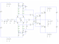
Here a picture from the simulator , i ll post the schematic later
on a relevant thread about symmetrical differential basic topology.
Actualy , only part of the compensation is made through
the fets input capacitances used as shunt.
Elektor s Crescendo used the same scheme but was hardly
stable , due to the cascoded VAS that cant be compensated
this way.
Anyway , perfs where not extraordinary but good enough
for the intended purpose , i.e , stage monitor amplifier for
my keyboards set.
Attachments
Giesbert's designs published in Elektor, ie., HEXFET Amp and IGBT Amp designs were done without compensation caps, were both symmetrical designs, and from personal experience and reported by others here, I can say that atleast the former was an unpredictable oscillator more than an amp. However, there are some reports that continuing to avoid compensation caps in the Vas, the amplifier was tamed by other means. The threads are around here in diyaudio.
Relying on the FET input capacitance for compensation has its issues considering the input capacitance is not constant and increases significantly as Vds becomes closer to saturation. Also Gm is a factor in this compensation scheme and it is not constant either. Certainly it is best to use some sort of compensation that remains at a fixed value and not dependent upon variable parameters. 
And that capacitance variation entails distortion that can become serious at higher frequencies.Relying on the FET input capacitance for compensation has its issues considering the input capacitance is not constant and increases significantly as Vds becomes closer to saturation. Also Gm is a factor in this compensation scheme and it is not constant either. Certainly it is best to use some sort of compensation that remains at a fixed value and not dependent upon variable parameters.
Here's an amp with no compensation. The reason it doesn't require any is because it is a folded cascode (only one gain stage).
Generally, an amp designed like this will have lower gain, higher distortion and higher slew rate than an amp with traditional Miller compensation. Not ideal characteristics for audio use.
Generally, an amp designed like this will have lower gain, higher distortion and higher slew rate than an amp with traditional Miller compensation. Not ideal characteristics for audio use.
Attachments
- Status
- This old topic is closed. If you want to reopen this topic, contact a moderator using the "Report Post" button.
- Home
- Amplifiers
- Solid State
- Power Amplifier WITHOUT compensation