'Anyhow, you can start by soldering IC sockets on the board and switch between ICs and compare them.
I do not know what is the level of your experience, and maybe you already know this:' Dankop.'
Quite experienced in construction although a bit rusty now. I recall that in the early '70s I couldn't afford the 'Texan' kit so I made my own pcb and built my own version of the amp into a cheap steel case.
'By the way, if the original electrolytic capacitors from the kit are 20 years old as I think they are, do not use them. Replace them with the new ones.'
Yes the components are >33 years old now, so I probably will change the caps. Although I am at this very moment listening to the radio via a Rank Arena A220 amplifier which was manufactured in 1970, has still all its original capacitors and produces almost flawless sound.
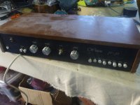
Resurrecting this thread - keen for a steer on getting this amp working. Please see various pics attached. I'm crashing at my sisters place and found this amp rummaging in the cellar. It smells like mould.
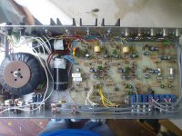
I saw it and thought "meh", then took a look at the back - all FET outputs - apparently its one of the first (if not THE first) FET output amps made. Dated from 1979 - it was a kit from a Practical Wireless mag. I found all the construction notes online and have posted relevant excerpts.
Take a look at the components used inside - I think this amp is well worth restoring - its has polystyrene caps throughout.
Issue: the sound is very faint and distorted in both channels. The amp powers-up fine thru the DBT.
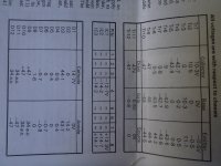
Fault finding: I have gone thru and taken all voltage measurements using the reference chart attached. All transistor voltages checked out OK.
However I am getting lower readings than I should be for D4 in both channels. I am getting 0.2V on both cathodes (instead of 0.5V) and 0.1V on both anodes (instead of 0.4V).
I am also getting a lower reading of 0.2V on both cathodes of both D5's, where I should be getting 0.4V.
I have removed every single transistor and tested them all - they all check out OK.
Output FETs - Im by far not an expert at testing these. However each type in both channels test the same. Plus I have tested all on a component tester and got these measurements:
- 2SJ48 #1: C = 719pF. Vt = 0.58V. P type MOS
- 2SJ48 #2: C= 719pF. Vt = 0.59V. P type MOS
- 2SK133 #1: I= 1.9mA. Vgs = 0.27V. N type MOS
- 2SK133 #2: I= 1.9mA. Vgs = 0.32V. N type MOS
Note that I am not getting the same readings for both types - ie: I wasnt able to get a VGS reading for the 2SJ types.
Question 1: Is there any other test that I can do (I tried multi meter tests but wasnt really sure what I was looking for) on the output FETs to check they are OK?
Question 2: The amp has 3 x TL072 input FET opamps - could these be the last remaining culprit? Can these get damaged easily? The voltages on pins 4 and 8 of all 3 of these however do check out OK - could they still be damaged though? If I have blown one or more of these, I could check (it seems) by dropping in some new TL2072 opamps as both a fault-finding measure and an upgrade.
Question 3: I have also set up the bias and that holds correctly for both channels. If there was an issue with the output FETs, could I expect to not be able to set the bias?
thanks
I saw it and thought "meh", then took a look at the back - all FET outputs - apparently its one of the first (if not THE first) FET output amps made. Dated from 1979 - it was a kit from a Practical Wireless mag. I found all the construction notes online and have posted relevant excerpts.
Take a look at the components used inside - I think this amp is well worth restoring - its has polystyrene caps throughout.
Issue: the sound is very faint and distorted in both channels. The amp powers-up fine thru the DBT.
Fault finding: I have gone thru and taken all voltage measurements using the reference chart attached. All transistor voltages checked out OK.
However I am getting lower readings than I should be for D4 in both channels. I am getting 0.2V on both cathodes (instead of 0.5V) and 0.1V on both anodes (instead of 0.4V).
I am also getting a lower reading of 0.2V on both cathodes of both D5's, where I should be getting 0.4V.
I have removed every single transistor and tested them all - they all check out OK.
Output FETs - Im by far not an expert at testing these. However each type in both channels test the same. Plus I have tested all on a component tester and got these measurements:
- 2SJ48 #1: C = 719pF. Vt = 0.58V. P type MOS
- 2SJ48 #2: C= 719pF. Vt = 0.59V. P type MOS
- 2SK133 #1: I= 1.9mA. Vgs = 0.27V. N type MOS
- 2SK133 #2: I= 1.9mA. Vgs = 0.32V. N type MOS
Note that I am not getting the same readings for both types - ie: I wasnt able to get a VGS reading for the 2SJ types.
Question 1: Is there any other test that I can do (I tried multi meter tests but wasnt really sure what I was looking for) on the output FETs to check they are OK?
Question 2: The amp has 3 x TL072 input FET opamps - could these be the last remaining culprit? Can these get damaged easily? The voltages on pins 4 and 8 of all 3 of these however do check out OK - could they still be damaged though? If I have blown one or more of these, I could check (it seems) by dropping in some new TL2072 opamps as both a fault-finding measure and an upgrade.
Question 3: I have also set up the bias and that holds correctly for both channels. If there was an issue with the output FETs, could I expect to not be able to set the bias?
thanks
Attachments
The opamps should be fine. If the supplies are correct then you should find essentially zero volts on all the other pins.
If the bias is OK and adjustable (should be around 100ma for lateral FET's) and the DC offset of the power amp is at approx zero volts DC then that all sounds good.
I would imagine the big issues with this amp at this age are the mechanical switches. Try feeding a signal straight onto the top of the volume control by linking direct from the input sockets to the volume control.
I have two of these amplifiers designed by Ted rule of Armstrong audio fame in my collection picked up from e-bay
Nice amp for the time
The front end Tlo72 leaves a bit do be desired but yet again for the money ok
I also repaired for a friend one of the kits when they were released
Great for a diy kit amp within its power rating
Trev
Nice amp for the time
The front end Tlo72 leaves a bit do be desired but yet again for the money ok
I also repaired for a friend one of the kits when they were released
Great for a diy kit amp within its power rating
Trev
This is fascinating. This 'Winton' MOSFET was the very first amp I built from scratch based on that WW article. I was 18, now I am 58! The amp is still sitting in my mothers flat in Zagreb, CRO, I think. How did this thread find me? Miracle I guess.
Very cool - it is pretty crazy finding one of these in little old NZ. Back then we had some pretty tight import controls - so this would have been a cost-effective way to build a good piece of kit most likely.
I have two of these amplifiers designed by Ted rule of Armstrong audio fame in my collection picked up from e-bay
Nice amp for the time
The front end Tlo72 leaves a bit do be desired but yet again for the money ok
I also repaired for a friend one of the kits when they were released
Great for a diy kit amp within its power rating
Trev
I would buy one of those two Wintons from you tomorrow. This amp brings back some good memories. Power MOSFETs in audio applications were hot in those days and this was my attempt to see what the rumor was all about. I think I had to order them from Maplin UK and of course build my own circuit board.
Last edited:
Hi Mooly, Yes i have complete kit. The output stage is 2sk133 / 2sj48 Hitachi. So probably the first amp kit to use mosfets.
Its about the same time Maplin brought out their lateral mosfet amp based on a Hitachi datasheet. A lot were made.
I was lucky enough a couple of years back to find an unmade kit on Ebay.
- Status
- This old topic is closed. If you want to reopen this topic, contact a moderator using the "Report Post" button.
- Home
- Amplifiers
- Solid State
- 1979 Amplifier kit