Greetings, I'll do my best to shed lite on my dilemna-I have a Bedini thats gone MAD after I installed BG caps on driver boards. Amp gets hotter on lft ch. than rt. ch. Has a hum. We have disconnected both driver bds. & ckd. power supply- both caps power up evenly within a 1/2 volt. Hook up left driver bd. only & get a1.5volt diff. reading on rt . power cap. This uses asplit power supply. b+ & B- give same values on Ps-caps. only wire common toboth bds hooked up is floating grd from PS board. hope this helps!!! Tkx Ronnie
Some of the factory modules have a trimmer pot on the board.
Iirc, the circuit has a standard Vbe multiplier with fixed resistors.
Trace it out?
I did not record the positions when I repaired one of them and a Strellioff (same thing).
If you swap the left module with the right, does the problem follow?
_-_-bear
Iirc, the circuit has a standard Vbe multiplier with fixed resistors.
Trace it out?
I did not record the positions when I repaired one of them and a Strellioff (same thing).
If you swap the left module with the right, does the problem follow?
_-_-bear
High DC Bedini 100/100
I have one 100/100, And Voltage on speaker terminals is about 150mv. It is high? What could be the problem?
I notice that increasing bias, this voltage go down, but consumption go very high. How much power consume in idle state? This is reading about 220Ws.
I see power transistors are not the same brand.
Thanks
Bedini's can take increasing the bias " if " the heat sinks can get rid of the extra heat. So using the touch test start increasing until you feel it's within a safe range, measure across 1 emitter then just set the other channel to match it.
When Bedini shop was in Paramount, CA. I used to go down there from time to time and he mentioned this to me.
Bedini's don't have a zobel network and the amp will eventually self destruct if you don't have a load hooked up... BTDT
Nice with tough electrostatic loads though
(check to see if the power supply has a 10watt resister on one leg to forward bias? My 150 mkII had this along with all mj15024 for outputs (from memory)
Regards
David
Bedini 100/100
David your memory serves you correctly. All Bedini's use MJ15024 transisters. Do you recall how much the bias factory setting is & how much appox. over can it be raised. I have MKII 150 & it is class AB & 100/100 is class A. Quite a difference in temp when they run. Regards R
David your memory serves you correctly. All Bedini's use MJ15024 transisters. Do you recall how much the bias factory setting is & how much appox. over can it be raised. I have MKII 150 & it is class AB & 100/100 is class A. Quite a difference in temp when they run. Regards R
SG
The 150 had puny stamped sheet metal heat sinks, hence John B.
set the bias accordingly (high bias class A/B). All Bedini's share very similar circuitry. You can run any bias level you want this side of too hot. According to John (at the time) bias level was not a ultra critical component on his amps. (kinda goes along with his personality... if you met him, you would understand)
I pulled those sinks off the 150 and installed huge sinks to run the bias up. When I mentioned to John what I was doing, (Now you can crank it up!) exact words That's what the 100/ 200 series accomplished with many more outputs and bigger sinks.
So do this, start running it up (bias) and set it until you can't touch the heat sinks for more than about 5 to 10 seconds.. Their TO3's and that should put you at what, maybe 55 to 60C. Set it lower if you want.
Really, don't worry yourself over this bias setting, but make sure everything else is in order. I think that series resistor was a 1ohm in one leg of the Power supply and measured differently in reference to ground. They should not be equal ( +/- sides) as I recall
I think he's in Utah and still refurbes them, Google it.
Regards
David
( LG At .25 emitters, those variations are decent enough )
Bedini Amp
Avwork, I can agree with your comment about John B. Used to do warranty work for him.
The biasing of the outputs may go a little easier if you mix and match transistors so each channel's emitter resistors have as close a voltage drop as possible. If say one channel you have 30, 45, 50, 28 mv, and the other channel has 25, 32, 55, 50 mv, then swap the transistors so one channel should now have 25, 28, 32, 30 and the other should be 45, 50, 55, 50. This will insure closer current sharing and even heat dissapation. John used to gain match all of his transistors as well as cut the top of the cans off and fill them with epoxy to reduce microphonoics.
Hope my explination made sense.
Regards, Steve
Today, i read the voltage in the speaker outputs, and their dropped from 160mv to 80mv!, the only thing I could realize is that on 160-200mv DC, the input was aprox 120V. Now, 115V.
Could this 5v change cause this amount of DC on outputs? (measured without any audio input, with or without inputs grounded).
Could this 5v change cause this amount of DC on outputs? (measured without any audio input, with or without inputs grounded).
bumping of epic proportions
but I have a Bedini 100/100 staring me in the face with a bad offset and a hum coming from it. Can't move around transistors because it's all on the one side, and hum will remain.
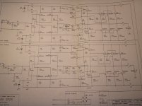
Anyone have any ideas, or could possibly provide schematics for even any of the amps from 25/25 up just so I have an idea of what I'm looking for? Thanks!
but I have a Bedini 100/100 staring me in the face with a bad offset and a hum coming from it. Can't move around transistors because it's all on the one side, and hum will remain.
Anyone have any ideas, or could possibly provide schematics for even any of the amps from 25/25 up just so I have an idea of what I'm looking for? Thanks!
appear to be in good condition? Visually??
Hardly necessary to shotgun the amp... the amp will run with just one pair of output transistors... into no load and a scope, or maybe an 8 ohm load, and not pushed on the bench...
So, you can identify the good or bad transistors that way.
Of course look for the requisite "0.6vdc" between the emitter and base of each device. If it's not there, then there is reason to suspect a bad device or something in that area being fried.
Any burnt resistors??
_-_-
Bedini 2525

anything about sound ?
I never heard Bedini .
looking at schematic ...... why I'm recollecting memory of Korato One ?

maybe because of that 2N3055 in bias stage
- Status
- This old topic is closed. If you want to reopen this topic, contact a moderator using the "Report Post" button.
- Home
- Amplifiers
- Solid State
- Bedini 100/100?? Need help to set bias