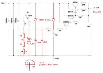
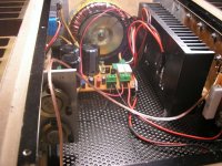
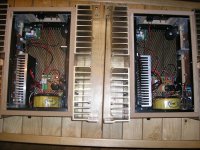
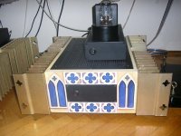
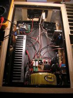
Hi, I would like to present you one old project of mine. It is a Germanium transistor SE class A amplifier. 32V power supply, 2A bias curent.
Do not ask me why germanium, because I do not know the real answer, it was probably one of those spite things
As I am compleat illiterate for electronics this was done whit little help from my friends I used russian GT813B transistors found in russian military radars
Original schematics was upgraded few times an from integrated full germanium amplifier derived a hibrid tube gain stage/Ge amp baffer stage.
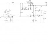
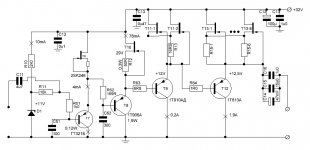
First the Ge amp baffer shematics and a few pictures
Do not ask me why germanium, because I do not know the real answer, it was probably one of those spite things
As I am compleat illiterate for electronics this was done whit little help from my friends
I used russian GT813B transistors found in russian military radarsOriginal schematics was upgraded few times an from integrated full germanium amplifier derived a hibrid tube gain stage/Ge amp baffer stage.
First the Ge amp baffer shematics and a few pictures
Attachments
-
 Ge Buffer MkII amp.gif9.8 KB · Views: 1,119
 -
 BB%20ispravljac.JPG54.6 KB · Views: 1,117
 -
 0.1.jpg101.1 KB · Views: 1,058
 -
 0.2.jpg112 KB · Views: 967
 -
 0.3.jpg119 KB · Views: 933
 -
 1.jpg189.9 KB · Views: 355
 -
 5.JPG104.2 KB · Views: 240
 -
 4.JPG114.7 KB · Views: 227
 -
 3.JPG66.8 KB · Views: 243
 -
 2.jpg94.4 KB · Views: 381
and some more....
Attachments
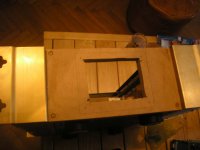
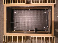
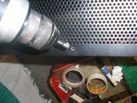
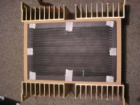
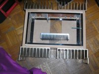
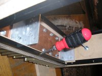
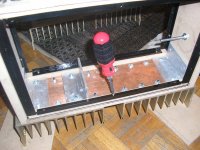
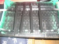
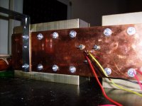
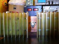
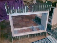
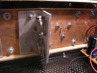
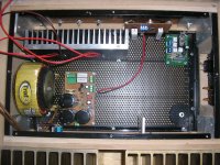
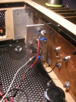
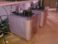
I used copper plates to mount transistors, I did nt want my tranis to be warmer than 50C, although these russkis are handling heat with no problem.
Attachments


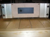
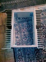
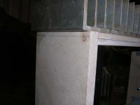
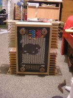
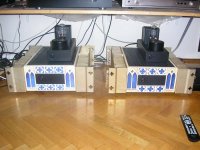
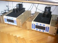
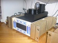
I have a friend who is a academic painter artist asked him to make an impression on front sides : so he made a gotic catedrale
asked him to make an impression on front sides : so he made a gotic catedraleAttachments

Last edited:
nicely done, woooo!!
Thanks, I did play with whole concept more than a year
Firstly it was all Ge including gain stage, it sounded like big juicy A class Ge ampBut when I started playing with hybrid I was completely blown away with the sound
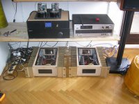
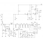
Then I experimented with different tube gain stages. On schematic it is 6n23p-ev with resistor load an cathode follower , and later on I changed to 6n30p-dp with CCS load and SLCF
Ge amp now works like F4, just a big juicy class A stove buffer

Attachments
I have a friend who is a academic painter artist
Very nice
I can imagine it sounds excellent with that circuit topology.
All you need now is a custom on/off switch to match the front panel
Key operated of course.
Attachments
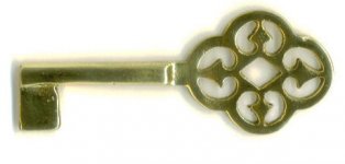

good idea, never crossed my mind...maybe, cast brass pieceVery nice
All you need now is a custom on/off switch to match the front panel
Key operated of course.
Fugly!
certainly is, cant agree more

Hi, I would like to present you one old project of mine. It is a Germanium transistor SE class A amplifier. 32V power supply, 2A bias curent.
Do not ask me why germanium, because I do not know the real answer, it was probably one of those spite things
As I am compleat illiterate for electronics this was done whit little help from my friends
The 1T813s are the most powerful high-frequency russian Ge BJTs, but, I was always afraid of using them in class A schematics. According to datasheet, at Ic=2A from the maximum static collector power dissipation curves, we have only maximum Vce=9V at Tcase=25C, and only 4V at Tcase=70C. In other words, it is not recommended to dissipate more than 15W on collector at static mode.
In my current disign I need to dissipate 33W (3A 11V) on p-n-p transistor, und using 1T813 is VERY seducing, by I am very afraid of testing 1T813 at this pawer rating.
In my current disign I need to dissipate 33W (3A 11V) on p-n-p transistor, und using 1T813 is VERY seducing, by I am very afraid of testing 1T813 at this pawer rating.
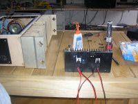
Hi Vladimir, the amp is dissipating about 33W with 2A bias current, and we haven't encountered any problems.
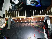
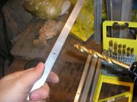
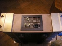
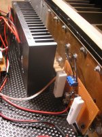
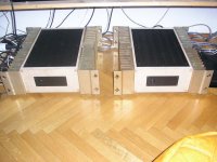
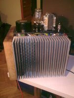
With good thermal pump with copper plate, transistor itself never got hotter than 52C even with ambient temperature quite above 25C. On the picture is the first model with really big radiators and even then it didn't cool down as it should, until I used cooper(without isolation, thermal paste only) Freq. characteristic was flat above 125kHz, only problem for me was finding a mached pair
Took me a while, but it was worthily.
Attachments
What have you done with those heatsinks from pictures above? Sold them i beleive...
Cases look very good,my opinion is that they would look even better if the mdf was also black but that is just my opinion-you ´re the one to judge about that!
As a mater of fact I have two pairs of those heatsinks, one pair is allready used for one project ,and second who knows...maybe some mad tube parafeed amp
If I knew it would be gothic cathedral I would made it black certainly, but now is late
maybe if my friend goes into another artistic faze Thanks, I did play with whole concept more than a year
But when I started playing with hybrid I was completely blown away with the sound
Then I experimented with different tube gain stages. On schematic it is 6n23p-ev with resistor load an cathode follower , and later on I changed to 6n30p-dp with CCS load and SLCF
Ge amp now works like F4, just a big juicy class A stove buffer
Hi, How did the 1T813 Ge/tube hybrid turn out?
-
What's next? A SiC amp that can glow red hot?
An externally hosted image should be here but it was not working when we last tested it.
Hi, all
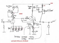
I confirm that there is something good added to sound with Ge output power buffer. Currently I use this version (quadro-darlingto) with PMC EB1i speakers, and it was first time that i heared really realistic (detailed, well resolved) bass from these speakers. Output impedance of this NoGNFB buffer is 17 milliOhms, that is not possible with any Si. Output capacitor should be around 100 000 uF, no way for only 10000uF. Similar output impedance achieved due to GNFB gives different, less realistic bass. Voltage amplification stage is based on 6p15p (EL803) tubes at penthode mode. Since it has output cap, the input cap in buffer schematics can be taken out.
I confirm that there is something good added to sound with Ge output power buffer. Currently I use this version (quadro-darlingto) with PMC EB1i speakers, and it was first time that i heared really realistic (detailed, well resolved) bass from these speakers. Output impedance of this NoGNFB buffer is 17 milliOhms, that is not possible with any Si. Output capacitor should be around 100 000 uF, no way for only 10000uF. Similar output impedance achieved due to GNFB gives different, less realistic bass. Voltage amplification stage is based on 6p15p (EL803) tubes at penthode mode. Since it has output cap, the input cap in buffer schematics can be taken out.
Attachments
- Status
- This old topic is closed. If you want to reopen this topic, contact a moderator using the "Report Post" button.
- Home
- Amplifiers
- Solid State
- Germanium Amp