Experience from using this circuit
Thanks for the work that went into developing this circuit. I have just installed it on my RIAA preamp. There was a significant thump when the amplifier was turned off. Since it is a tube amplifier, there is no thump when it turns on.
Since I believe that this thump always comes from the preamp, I installed NC contacts shorting out the amplifier outputs. Since the signal is low power, I used a small ‘Zettler AZ822-2C-12DSE’ relay.
I followed your circuit and had a series resistor of 3.8k. the result was a thump approximately 60mS in duration (cut off by the relay contacts closing) and commencing approximately 50mS after the power was disconnected. It appears that the circuit was closing the contacts in approximately 110mS after power was disconnected.

I therefore went and revised the circuit so that the relay would close contacts (drop out) at approximately 25mS. The concern was that the holding current across the relay was approaching 3mA and I was concerned that this current was getting too low for the triac to stay conducting.
The result I settled on was adding a parallel resistance of 150 ohms across the relay coil and sized the series resistance at 470 ohms. Testing the circuit, I found the relay drops out at 20 to 28 mS and the minimum voltage across the relay coil is approximately 3.2Vdc.

The revised circuit is installed in the amplifier and there is no thump when the amplifier is turned off. I will use this circuit again!
Thanks for the work that went into developing this circuit. I have just installed it on my RIAA preamp. There was a significant thump when the amplifier was turned off. Since it is a tube amplifier, there is no thump when it turns on.
Since I believe that this thump always comes from the preamp, I installed NC contacts shorting out the amplifier outputs. Since the signal is low power, I used a small ‘Zettler AZ822-2C-12DSE’ relay.
I followed your circuit and had a series resistor of 3.8k. the result was a thump approximately 60mS in duration (cut off by the relay contacts closing) and commencing approximately 50mS after the power was disconnected. It appears that the circuit was closing the contacts in approximately 110mS after power was disconnected.
I therefore went and revised the circuit so that the relay would close contacts (drop out) at approximately 25mS. The concern was that the holding current across the relay was approaching 3mA and I was concerned that this current was getting too low for the triac to stay conducting.
The result I settled on was adding a parallel resistance of 150 ohms across the relay coil and sized the series resistance at 470 ohms. Testing the circuit, I found the relay drops out at 20 to 28 mS and the minimum voltage across the relay coil is approximately 3.2Vdc.
The revised circuit is installed in the amplifier and there is no thump when the amplifier is turned off. I will use this circuit again!

Hello Mooly,
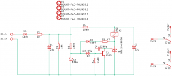
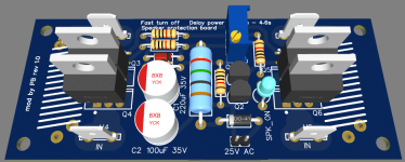
I was looking at practical implementation of circuit on a PC board. Here is one. Could you let me know if any changes required.?
regards
prasi
I was looking at practical implementation of circuit on a PC board. Here is one. Could you let me know if any changes required.?
regards
prasi
Attachments
Last edited:

Thanks for this circuit. I built it and it works perfectly.
When upgrading my old subwoofer amp I rebuilt its active low-pass filter and added balanced output from the filter to the amplifier. Now it seemed that the amplifier was more prone to reacting to imbalance of the power supply after turning it off and consequently caused crackling noises in speaker after turning it off. I measured that the negative and positive supply weren't dropping equally, so that could be the reason. Now with Mooly's circuit added to the mix it turns output off immediately. I didn't connect speaker output to the relay, but the amplifier module's standby input (which turns off the amp when earthed).
I had about 38V AC on one of the secondaries that I connected to the circuit. I used a 24V relay and 15V zener. R6 4.7 kohm, which seems to turn the output off just about right. The Triac was hard to find, but I found the BTA16-600SW on ebay.
And FYI. I did try a modification of the circuit where i energized the relay when voltage loss was detected. 'Relay drop out circuit' still acceptable response with the original circuit, but there is a hint of a thump, so wanted to improve upon it. Turned out that the one additional device required in the circuit i designed added delay, swamping the improvement of fast energizing the relay coil with a higher voltage from a capacitor. I wanted to try to shave a few more milliseconds off the response, but all was for not.... .
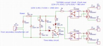
I wonder if this will work with optoelectric based relay? I have sketched schematics in LTspice, but I think I messed up with some values for time delay... Anyways, I am attaching it - hopefully someone can help on it -thank you!
Attachments
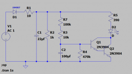
You have lots of ripple current in the LED and it would probably sound weird as it turns on. Look at the LED current.
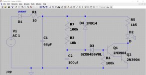
Try this. The Zener allows a decent charge curve to develop on the cap. The diode discharges the cap quickly when the rail collapses. The LED current may still be on the high side here and the reservoir cap might be OK with a 47uF.
Try this. The Zener allows a decent charge curve to develop on the cap. The diode discharges the cap quickly when the rail collapses. The LED current may still be on the high side here and the reservoir cap might be OK with a 47uF.
Attachments
Awesome! Thank you Mooly for your help! Will dig into this now...You have lots of ripple current in the LED and it would probably sound weird as it turns on. Look at the LED current.
Try this. The Zener allows a decent charge curve to develop on the cap. The diode discharges the cap quickly when the rail collapses. The LED current may still be on the high side here and the reservoir cap might be OK with a 47uF.
The Zener is not critical but should be high enough to allow a decent voltage to develop across the timing cap. So 8.2 or even 12v should work fine. The higher the Zener voltage and the less base current is available and so yes, you do need two transistors for this.
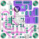
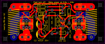
Here is the PCB. I decided to include Thiele network on the protection board as it moves it closer to the output terminals inside the amp case.
Attachments
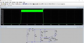
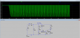
The smaller the value of C1 and the quicker the relay drops out on power off. The 10 ohm is to limit ripple current in the cap because without it the ripple may exceed a small caps ratings. It makes a massive difference.
I tried using 100 ohm for R1 and 100uF for C1.
Correct me if I am wrong, but it looks like there will be around 70mA current on the resistor (green on the graph) - that is with 100 ohm value. Voltage coming in is 24V. So we get 24V * 0.07A = 1.68 W. Is this correct?
With 100uF cap, the delay is around 10.129s - does it mean 129ms delay? Is that enough or I should go for smaller cap?
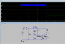
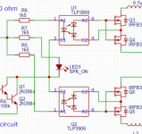
It looks like I can reduce ripple by connecting each LED in parallels with adding 1.5k resistor in series for each LED - in my case three. Two optocouplers to drive mosfets relay, and one to indicate speakers on.
Thank you,
Pavlo
Attachments
Last edited:
- Home
- Amplifiers
- Solid State
- Simple Universal Speaker Delay Using A Triac