HI!
Has anyone here built the Compact Power Amplifier from Elektor may 1997?
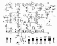
Take a look at the schematic. It's quite special in many ways. It uses current feedback instead of voltage feedback. It also incorporates Toshiba IGTB's for drivers. These IGBT's are made especially for audio and should sound very good indeed.
Any comments?
Best,
Peter
PS: I can mail the whole article as a PDF-file if some of you would like to read it.
Has anyone here built the Compact Power Amplifier from Elektor may 1997?
Take a look at the schematic. It's quite special in many ways. It uses current feedback instead of voltage feedback. It also incorporates Toshiba IGTB's for drivers. These IGBT's are made especially for audio and should sound very good indeed.
Any comments?
Best,
Peter
PS: I can mail the whole article as a PDF-file if some of you would like to read it.
Attachments
I have build one
I have build this amp about four years ago. There is a lot of problems with it. You have to carrefully match input transistors to get a low offset, and amp was unstable. I have burn a lot of these high price GT20D101 and 201, so if you want to build it at first buy a cheap power mosfets to make a tests. I have problems with parts, because I use an elektor pcb. If you want make this amp, I have an proffesional made boards boards ( 3 or 4 pices ). I really don't know how it's sounds. I never ran two channels at one time.
Today I see that output stage of this amp is not good. It is something call here as CFP ( or sth ). A lot of problem with thermal stability ( DC servo is not a good solution ), and has a large amount of feedback ( last two stages ), so going to be unstable.
I can't say anything about the above experiences, but pls note that the drivers are regular bipolars, not IGBT. Only the outputs are IGBTs. The feedback is actually voltage feedback (the output voltage is returned to the input side) and is developed into a voltage and combined with the servo output. Because of the servo, input matching should not be required for DC offset (it may give better performance sound-wise though).
Jan Didden
Jan Didden
CFP output stage using IGBTs is scary. IGBTs have 2 hf poles in their frequency response, when presented with a low impedance load one of them moves downwards low enough to cause issues with loop stability.
I have built follower o/p stages using these Tosh IGBTs and IMO they sound just like bipolars.
CFP can be made to work well - it's fine in the ESP P3A for example (althought that design needs an output inductor).
You should also be aware of the latch up possibility of these IGBTs under high current conditions - 20A or so - could be less if they are hot. I would recommend some sort of current limiting to be on the safe side.
Dave
Well, we may have a semantic issue here, but clearly the signal fed back is a representation of the output VOLTAGE, whatever the Elektor article says. Isn't that the definition of voltage feedback? This will stabilise the output voltage.
Now if I have a power amp and put a resistor from the speaker return to ground and feed that signal back, it is a sample of the output current so I would call that current feedback, it stabilises the output current.
Jan Didden
Now if I have a power amp and put a resistor from the speaker return to ground and feed that signal back, it is a sample of the output current so I would call that current feedback, it stabilises the output current.
Jan Didden
Well, we may have a semantic issue here, but clearly the signal fed back is a representation of the output VOLTAGE, whatever the Elektor article says. Isn't that the definition of voltage feedback? This will stabilise the output voltage.
No. this input stage is a current feedback one, it has 2 input nodes, one has high input impedance(the non-inverting input) and one has low input impedance(the inverting input) so this amp is controlled by current(that’s why the amplifier uses so low value resistors on the feedback network).
Now if I have a power amp and put a resistor from the speaker return to ground and feed that signal back, it is a sample of the output current so I would call that current feedback, it stabilises the output current.
this creates a high output impedance, and the amp becomes a current output amplifier or transconductance amplifier... it has nothing to do with the input stage...
Best Regards
Ricardo
Jan i think i can see your point, but in case of that amplifier it´s obvious that the amp is controled by current. Here it is a very nice explanation to the forum menbers o dont understand this type of amplifiers:
"The op-amps we’ve presented to this point all share certain characteristics. Among these
are a very high input impedance (both differential- and common-mode), implying voltagemode
operation. As a consequence, capacitance is an extremely important limitation on
bandwidth. Op-amps of this type have dominated the amplifier world since the very first
vacuum tube implementations, and generally exhibit constant gain-bandwidth products.
As a result, an increase in closed-loop gain must be paid for by a decrease in closed-loop
bandwidth. Furthermore, the need to charge up node capacitances with limited currents
produces the well-known slew limitations that vex conventional op-amps.
If high impedance is not strictly required (indeed, if it is purposefully abandoned), one
may evade the tyranny of constant gain-bandwidth and, to a remarkable extent, limited
slew rate. One class of amplifiers that exploits this idea is the so-called current feedback
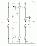
amplifier, a simplified schematic of which is provided in Figure17. Although the basic
topology actually traces back to 1930s-era vacuum tube circuits (including HP’s famous
Model 200 oscillator), a widespread appreciation of the attributes (and limitations) of this
topology had to await the 1980s, when companies such as Comlinear (now a part of
National) and élantec popularized the circuit.
As can be seen, the noninverting input is high impedance, but the inverting one is not. In
fact, the inverting input is actually the output of an emitter follower, whose input in turn is
the noninverting terminal of the amplifier. Any differential input voltage causes a current
flow (and an exponentially sensitive one at that). This current flows through the inverting
input, and its mirrored version causes a voltage to be developed at the high impedance
node (collectors of Q6/Q9). Thus, we may say that the output voltage is proportional to the
current that flows through the inverting input terminal. This observation is the key to
understanding how to use and analyze circuits using these types of amplifiers."
Cheers
Ricardo
"The op-amps we’ve presented to this point all share certain characteristics. Among these
are a very high input impedance (both differential- and common-mode), implying voltagemode
operation. As a consequence, capacitance is an extremely important limitation on
bandwidth. Op-amps of this type have dominated the amplifier world since the very first
vacuum tube implementations, and generally exhibit constant gain-bandwidth products.
As a result, an increase in closed-loop gain must be paid for by a decrease in closed-loop
bandwidth. Furthermore, the need to charge up node capacitances with limited currents
produces the well-known slew limitations that vex conventional op-amps.
If high impedance is not strictly required (indeed, if it is purposefully abandoned), one
may evade the tyranny of constant gain-bandwidth and, to a remarkable extent, limited
slew rate. One class of amplifiers that exploits this idea is the so-called current feedback
amplifier, a simplified schematic of which is provided in Figure17. Although the basic
topology actually traces back to 1930s-era vacuum tube circuits (including HP’s famous
Model 200 oscillator), a widespread appreciation of the attributes (and limitations) of this
topology had to await the 1980s, when companies such as Comlinear (now a part of
National) and élantec popularized the circuit.
As can be seen, the noninverting input is high impedance, but the inverting one is not. In
fact, the inverting input is actually the output of an emitter follower, whose input in turn is
the noninverting terminal of the amplifier. Any differential input voltage causes a current
flow (and an exponentially sensitive one at that). This current flows through the inverting
input, and its mirrored version causes a voltage to be developed at the high impedance
node (collectors of Q6/Q9). Thus, we may say that the output voltage is proportional to the
current that flows through the inverting input terminal. This observation is the key to
understanding how to use and analyze circuits using these types of amplifiers."
Cheers
Ricardo
Attachments
The Elektor circuit topology strongly reminds me of current Accuphase amplifiers... The high power design from Elektor (from 1999 I think), which was derived from this circuit, was even closer.
And yes, it is current feedback. The input stage is actually a buffer, and the feedback signal is tied to the output node of the buffer. This leads to reduced phase shift in the feedback network which improves the phase response at higher frequencies. One big problem with this kind of input stage is the poor PSRR which is why they stuffed the LMxxx regs in there.
However, to me it looks they just wanted to be cool and use CFB and IGBT - they didn't know how to properly implement it for audio. I've experimented with the GT20Dxxx Toshiba parts. Forget them. Really. Nelson Pass had some comments on IGBTs for audio, too.
AMT-freak said:The Elektor circuit topology strongly reminds me of current Accuphase amplifiers... The high power design from Elektor (from 1999 I think), which was derived from this circuit, was even closer.
I have the original 1997 article, but I missed the 1999 higher power article. Do you or anyone else have this article or know where I could find it online?
However, to me it looks they just wanted to be cool and use CFB and IGBT - they didn't know how to properly implement it for audio.
I was a regular reader of Elektor around the time this article was published, and they had several amplifiers that used IGBTs. Maybe they were sponsored by Toshiba or something
")
The reason for using CFP was that they could have a gain of 2 in the output-stage and so make up for the lower supply rails on the input stage.
I think it should be possible to substitute the IGBTs with lateral mosfets, has anyone tried this? Maybe R32 and R36 need to be changed in the process. Someone with experience with lateral mosfet might be able to answer this.
Well,
can anyone here tell me what's all wrong with those IGBT's?
I've built seven amplifiers with IGBT's, 5 of them with 1 pair of GT20's and 2 with 2 pairs of IGBT's.
If you use 2 pairs it's necessary to match them very well since there can be pretty high differences between 2 GT20D101's or 2 GT20D201's...
They all worked the first time, no problems with blowing or whatsoever. The sound is very good, not as good as my Thel's, but they are a lot more expensive, so I don't think you can compare them.
So...what is the problem?
Grtz, Joris
As I see it, it is a standard Voltage Feedback Design, with a lot of "difficulties" due to the matched input transistors etc.
Please tell me the reason to use such a design
It may perform very well, however it requires almost perfect operating conditions to do so...... And if these are not present????
Please tell me the reason to use such a design
It may perform very well, however it requires almost perfect operating conditions to do so...... And if these are not present????
I found that they are not very reliable and tend to blow up without a good reason. I got a bunch of them in original packaging from Toshiba and they were all defective. I really don't understand this as IGBTs are manufactured in many flavours for a variety of demanding switching applications where they proved to work reliably. Maybe I just had bad luck, or maybe the particular model GT20Dxxx has problems.
IGBTs do have some serious problems when you look at them from an audio point of view. Frist of all, I don't see why having a hybrid of FET and bipolar in one package (with at least one leg missing) is an advantage. Also, they cannot be paralleld. Ok, they can, but the differences in Vg make it a major hassle and it is simply not worth doing it, except you want to prove yourself that you can build amplifiers out of everything. They are not very stable and behave funny at certain frequencies, depending on application. Elektor had to write a follow-up with some corrections to their first IGBT project. To put it simple, they combine the flaws of both FET and bipolar in one expensive package.
Your mileage may vary.
ACD:
Mark Alexander elaborates extensively on the CFB principle in his amp, which you can find amongst the AD application notes...
Sorry to disappoint you but it isn't standard or voltage feedback. It is CFB by definition. There are several advantages to CFB which the more knowledgble guru's could elaborate on, but perhaps most notably the extended frequency response / GBWP.As I see it, it is a standard Voltage Feedback Design, with a lot of "difficulties" due to the matched input transistors etc.
Mark Alexander elaborates extensively on the CFB principle in his amp, which you can find amongst the AD application notes...
- Status
- This old topic is closed. If you want to reopen this topic, contact a moderator using the "Report Post" button.
- Home
- Amplifiers
- Solid State
- Compact Power Amplifier from Elektor