As per title I am planing the build of a 1987 power amp from an article on Elector Electronics magazine.
I'm building it for 2 reasons:
First I know it works because I build it before (when the article came out)
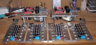
Second I have all the most expensive parts like 1 huge heatsink (400x450mm) that I had cut in 2 today, 1 huge toroid transformer (2kw) with the right output voltage, 4 x 15000uF x 120V capacitors and 18 2sk175/2sj55 pairs of mosfets.
To start the build I have 1 question for now.
What is the best way to attach the TO3 mosfets to the flat heatsink ?
I don't want to use "L" profiles because I want to keep the case as close to Standard as possible (+/- 430mm wide).
Any Ideas ?
This is going to be a slow build because I have a day job and I'm not in a hurry
Ric
I'm building it for 2 reasons:
First I know it works because I build it before (when the article came out)
Second I have all the most expensive parts like 1 huge heatsink (400x450mm) that I had cut in 2 today, 1 huge toroid transformer (2kw) with the right output voltage, 4 x 15000uF x 120V capacitors and 18 2sk175/2sj55 pairs of mosfets.
To start the build I have 1 question for now.
What is the best way to attach the TO3 mosfets to the flat heatsink ?
I don't want to use "L" profiles because I want to keep the case as close to Standard as possible (+/- 430mm wide).
Any Ideas ?
This is going to be a slow build because I have a day job and I'm not in a hurry
Ric
Last edited:
'Looks wonderful but quite an expensive solution, assuming they are custom milled profiles in lieu of L section ones. If you have access to a machine shop, great but I see some serious cash needed, as one who has had to cost engineering work.
Perhaps you'll also consider fabricating those massive bars from 2 pieces of plate or plate and rectangular bar. That will be a lot simpler and cheaper.
Perhaps you'll also consider fabricating those massive bars from 2 pieces of plate or plate and rectangular bar. That will be a lot simpler and cheaper.
The name on the article was "1000 watt amplifier" and was published in 1987.
The power of 1000W is the bridged power the rated power was/is 250W 8ohm or 500W 4ohm or 1000W 8ohm in bridge mode.
It uses 4 pairs of 2SK175/2SJ55/channel.
I will post the schematic as soon I sort a few things (soon).
Ric
The power of 1000W is the bridged power the rated power was/is 250W 8ohm or 500W 4ohm or 1000W 8ohm in bridge mode.
It uses 4 pairs of 2SK175/2SJ55/channel.
I will post the schematic as soon I sort a few things (soon).
Ric
Last edited:
I will stay around ... and so is thermal runaway ,and oscillation .
That will be an interesting battle to watch .
i cannot offer advice ... but i can only say one thing ... Match very very carefully any semis you are willing to use .stay as close is possible to the original semis ...
If you decide to ventilate the project make sure that the cool air ventilates only the outputs ...even your breath above the drive board will change idle and offset .
Happy regards
sakis
I guess this is this one....
This iteration of their Crescendo amp still use a random stabilization
using the output stage capacitance as a shunt compensation.
So you are saying that the amp is unstable ?
But I build this one when the article came out in 1987 and it was working fine without problems and as far I know the amp is still going strong.
So why do you say that ?
Actually I was planing on put a front end like the ones on the nelson Pass Alephs amps.
But for that I will need help
As for the heatsinks they going to be the sides of the case (220x400x40mm)
Is going to be for stereo use and nothing very demanding, only building it because I have all this stuff laying around in my shed and the transformer alone is worth over 150 pound
Last edited:
did you have the means to test it properly ?
did you scope the amp
do you have sets of measuring ( bias . offset currents and voltage here and there ?)
Did you have the same experience like you do today?
Or was enough that the amp produce music
At the time my personal approach was even worst ...now days i read more try to learn more and focus in things that my skills are able to produce .
The all family was a huge problem starting from the 100W (????) BDW 83-84 amplifier then with various crescendo bul and so on .
as you said if the duty is lite and nothing very demanding then yes it might as well work Still then ita will be a waste of parts to produce something so big to operate for domestic listening ... Make a DX amplifier ...
sorry for the tone but i had to repair and stabilize quite a few of them and trust me it wasn't an easy task .
Kind regards
sakis
Well in 87 I was only 18
But I remember that the bias and offset was stable and I did a few parties with it and it run hours without any problem.
In one of this parties it run from around 9pm to 6 in the morning without a glitch.
Another thing i remember is that back them I spend a small fortune in building it.
Now about this project was do you recommend ?
Transformer is 2000W with 55/0/55V output and I want to use the Hitachi mosfets (2SK175/2SJ55).
I am open to suggestions
How about a A75 with laterals ?
I can always take some windings from the toroid...
The heatsinks can take a load of heat (400Wx220Hx40D)
I know that the bias with the lateral are not the same as with the IRF mosfets but that is not a problem.
Last edited:
So you are saying that the amp is unstable ?
It is components dependant.
For some reasons the authors did rely on intrinsic shunt compensation
to get the amplifier stable , so the more the output device number the more
compensation wich is why this one works probably better than the
Crescendo that did have less output devices....
Anyway, eventual instability can be easily cured by adding two
compensation capacitors at the relevant nodes , you ll see at the end
of your build if they are necessary or not.
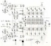
This amp already as the compensation capacitors in the output mosfets
If you look at the top mosfet bank in the schematic you will see a small capacitor going from gate to source and gate to drain.
I know and read before that this type of mfets tend to oscillate without them.
One of this discussions is the thread about the Golmund Telos amplifier that uses the same output mosfets.
Ric
Last edited:
Properly designed amplifier should and must work with out them . ( extensive stabilization caps ) These are notorious sonic killers .
I can give you 10-20 schematics working without them and also i guess you may find them your shelf ...internet is full of them .
Kind regards
sakis
I can give you 10-20 schematics working without them and also i guess you may find them your shelf ...internet is full of them .
Kind regards
sakis
I built this amp with 2SK1058/2SJ162 pairs. Pinout is different from the board layout. Could not get it to bias properly. But the amp did play and was quite a bass champ. This is very close to the Crescendo layout except that Zeners are used in the input stage and the cascoded drivers are Mosfets.
You could probably check the SSA thread and see if you could modify this to follow the changes that Esparado made to his Crescendo. If you succeed with a bit of help from informed folks here, you will end up with a High Power SSA with Lateral Mosfets and the sound significantly better than the original.
You could probably check the SSA thread and see if you could modify this to follow the changes that Esparado made to his Crescendo. If you succeed with a bit of help from informed folks here, you will end up with a High Power SSA with Lateral Mosfets and the sound significantly better than the original.
Well...
I had a look at the SSA thread and apparently they are far from the finished amp.
Yes many question how to improve, raise power and this and that but the amp is still in the development stage (+/- 1 year).
My main objective is to use the parts I have in my parts bin especially the 2SK175/2SJ55 transistors and transformer.
Yes I know there are many schematics around that don't use capacitors to stabilize the output transistors and probably better then the one from Elector.
I do have the schematics for the C-Audio SR606/707 and it doesn't use caps in the output transistors.
I'm going to finish the case for now and keep looking for something for the Hitachi mosfets.
Got some aluminium today and realized I ordered the wrong thickness, oh c**p.
Ric
- Status
- This old topic is closed. If you want to reopen this topic, contact a moderator using the "Report Post" button.
- Home
- Amplifiers
- Solid State
- Building a 1987 power amp