Hi,
I would like to investigate about the actual/perceived/imagined superiority of current feedback, and possibly to pinpoint what exactly makes it superior (if indeed it actually is).
As a study subject, I propose to use a very simple, quasi-canonical form of a CFB amplifier, the CFP with gain.
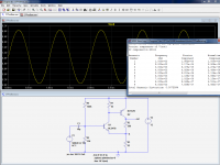
The two first pics show the linearity and frequency performances of the circuit.
The interesting thing with the sim is that it allows the transformation of this ideal CFB amp into an identical ideal VFB stage.
That can be done with an arbitrary voltage source (the next two pics).
As could be expected, the linearity has improved thanks to to the increased loop gain, but somewhat more surprisingly the bandwidth also increases.
I recall at a circuit in that kind for a simple preamp (line) stage. By listening tests the value of R1 exerted a great influence to the sonic performance.
The best sonic results were achieved by such values, that the idle current for Q1 goes up to 10-15mA (instead only 1-2mA in your proposal).
By simulation no significant differences were observed.
What reasons could be responsible therefore ?
Apart from slew rate a CFB is no better than a VFB and usualy
not as good in matter of linearity contrary to your sayings
wich was the point that i didnt agree with.
Indeed , the best opamps in this matter are VFBs.
As for high slew rate, it is pointeless if linearity is worse ,
wich is often the case with CFBs.
Please name the VFB opamps that can beat the THD performances of CFB. CFB is in actual fact as linear and even more so than VFB. Show me a VFB that can do - 90 db THD at 1Mhz. There are many of CFB that can do this and some do even better. I think you need to do some research regarding CFB. When you have slewrate and linearity which is better than VFB it makes for excellent topology.
If what Im saying is wrong please provide proof, name the parts or show us the circuits. VFB is better in some respects but its nothing to do with linearity or slewrate.
Please name the VFB opamps that can beat the THD performances of CFB.
For example http://www.ti.com/lit/ds/symlink/ths4271.pdf -92dB @30MHz
Which doesn't mean that VFB is anywhere better than CFB. CFB is just a different approach, with pros and cons (cons examples: offset, noise).
That is quite surprising: R1 does have a huge impact on many aspects of the circuit, the linearity, loop gain, slew rate etc.By simulation no significant differences were observed.
What reasons could be responsible therefore ?
For example if R1 is doubled in the example, from 560 ohm to 1K, the THD is reduced by a factor of ~3.
There are many tradeoffs of impedance, gain, bias currents etc in this circuit, and the value of R1 does have a pivotal role in them
Attachments
Please name the VFB opamps that can beat the THD performances of CFB. CFB is in actual fact as linear and even more so than VFB. Show me a VFB that can do - 90 db THD at 1Mhz. .
Low THD at 1Mhz doesnt mean lower THD at audio frequencies ,
wich is the case that interest us.
Low THD at 1Mhz doesnt mean lower THD at audio frequencies ,
wich is the case that interest us.
Yes it does in 99,99 % of cases and what is even more important is the fact that typically you dont see a sharp increase in THD at frequencies higher than 1k as one usually does with VFB. The THD curve is virtually flat, from DC till around 20Khz. What is the use of only having low THD at 100 to 500 hz.

cfb to vfb
Elvee
Saw this one and thought you might enjoy it:
http://www.ti.com/lit/ds/symlink/lm7171.pdf
See the simplified diagram near the bottom.
-Antonio
Elvee
Saw this one and thought you might enjoy it:
http://www.ti.com/lit/ds/symlink/lm7171.pdf
See the simplified diagram near the bottom.
-Antonio
A thing that I have looked at for the LM7171 would look something like this.
This is intended to be a high q bandpass filter/buffer.
The first two devices are connected as a transconductance amplifier to provide high impedance drive to the filter, and the output device is connected as a q multiplier.
rcw
This is intended to be a high q bandpass filter/buffer.
The first two devices are connected as a transconductance amplifier to provide high impedance drive to the filter, and the output device is connected as a q multiplier.
rcw
Attachments
Yeah, nice one: it shows that in reality too the differentiation between the two categories is dwindling.Elvee
Saw this one and thought you might enjoy it:
http://www.ti.com/lit/ds/symlink/lm7171.pdf
See the simplified diagram near the bottom.
-Antonio
It is probably unfair to compare an amp run from clean power with an amp run from dirty power. Whether or not your LTP with global negative feedback can hide a lot of power noise along with a little bit of your signal, highlights the very real problem of using power noise rejection as an excuse for cheap abbreviated power supplies. The resulting problem is harder to measure by design with many generations of amplifiers repeatedly refined for the purpose of hiding errors from scopes (too much like selecting beer flavor by forensic analysis). However, the consequences of dirty power inside the feedback loop remains obvious to the ear as a distorted or shrunken perceived soundstage size. The LTP can be hobbled and clean power can be used. Note that there's less distortion of soundstage when using global negative feedback with NTP, SSA and Singleton input amplifiers. Therefore, the concept of global negative feedback wasn't at fault, and an LTP might not be blameless after all.the reason is feedback has no clue if it is timbre of instrument or a power supply noise that NFB is currently suppressing")
R1 sets the quiescent current through Q1. Alternatively, it sets the point where Q2 begins to turn on. Boosting the current in Q1 boosts the transconductance of the pair, which is roughly given by (Q1 gm) x R1 x (Q2 gm) at low currents and (Q1 gm) x (Q2 beta) at higher currents. The transition between these two regions depends on where the input resistance of Q2 starts to load R1. [Roughly, R1 ~ (Q2 beta) / (Q2 gm)]Elvee said:That is quite surprising: R1 does have a huge impact on many aspects of the circuit, the linearity, loop gain, slew rate etc.
In each case, gm varies with current in the usual BJT way.
I wrote an article about this for Wireless World about 10 years ago, but unfortunately it is not on the web and I think they still have copyright in it.
That would be interesting for many here to read, DF. It seems absurd that an inaccessible archive forbids further distribution of its content for 25 years. Then there is your own perpetual copyright over the material. D. Self has the same issue with posting even ancient tube material from E&WW magazine on his website....I wrote an article about this for Wireless World about 10 years ago, but unfortunately it is not on the web and I think they still have copyright in it.
Cyril Bateman's material is everywhere about the web now so perhaps Svetlana would entertain the idea of posting the material on your site?
let me throw in a couple things to think about --- Most VFB amps have a rising thd as freq goes up. Cfb amps have a flat thd over a wide freq range. In power amps especially, the high freqs are not as clean sounding as the lower freqs. But cfb circuits have the same sound character across the bandwidth. Cfb circuits dont depend so much on a Cdom. -RNM
Phase deviation at low F and THD at high F
Fact 1:
Nobody talks about transfer functions; about that we have a first pole at low freq in VFB and the first pole in CFB is more more higher .This will shift the phase for VFB below 20khz with -90 degrees ,but in CFB ,because the pole is at a freq very high ,we have no phase shifting in all audio band !
So even the gain is high at VFB at low freq ,the phase is shifting from 0 to -90 in audio band ;It starts with 180 in DC to very low freq ,then at about 10-200Hz we have 45 degrees(the pole) ,and after we have 90degres at 1-3 khz.
All these in open loop .
So if the designers consider the open loop gain for thd why they don't consider also the open loop phase ? Why accuphase amps with CFB sounds better ?
Also phase for negative feedback input in VFB is turned by 2 poles but in CFB is turned only once and this is at high freq.If in VFB we have 2 common emitter stages for the negative feedback ,in CFB we have a common emitter and a common base .
So logical is to choose the circuit with less transformation of the negative feedback signals .Because the non-linear distortion is important .
So the CFB at this hour has high speed ,high bandwith ,excelent phase response .
The VFB has speed but not as much as CFB ,low bandwith ,poor phase response .
May be we don't need much speed,may be 50V/us is correct for 100W SACD information .But why not double it ?
Fact 2 :
What about the THD ?
Well , we can say that the THD is almost the same with VFB and CFB ,but at low freq .
Is more important the THD at high freq than at low freq ?
I am thinking only at the fact that the low frequencies in music is at least 3-5 times higher in amplitude than the high freq and that the SNR is also higher at low F and low at high F.
So to have a good separation between the instruments we need more low thd at high freq compared to the thd at low freq .The small amplitude signals in music are the high freq signals majority !
When we listen music we are searching to have good separation of instruments ,we are searching also to hear the complex pieces clear ,clear means that the high amplitude signals don't distort the small signals .The brain recognize the high amplitude easy but the low amplitudes (which is the high frequencies ) is a little more hard to understand .Also the small amplitude signals(HF) have a smaller SNR .
So then we need more accuracy at high frequency .
And here again the CFB has a lower thd at high freq compared with the VFB .
Fact 3.
Negative feedback circuit should have a high speed ?
What speed will have the negative feedback signal to compensate the output signal in CFB compared to VFB ?
So what topology should we choose ?
Last edited:
The fact of labelling preconceptions, personal beliefs and prejudices as facts doesn't change their nature or make them true.Fact 1:
..../....
That is a fact
The fact of labelling preconceptions, personal beliefs and prejudices as facts doesn't change their nature or make them true.
That is a fact
Elvee ,I think that all 3 "preconceptions" are theoretical correct .
Please say where I am wrong in these theories .
Elvee ,I think that all 3 "preconceptions" are theoretical correct .
Please say where I am wrong in these theories .
Catalin next someone else will post a VFB opamp with better specs than CFB ones in another lame attempt to convince or mislead, what they do not say is that these VFB opamps consist of three opamps in one chip like the one Waly posted to manage what one CFB opamp can do.
Catalin next someone else will post a VFB opamp with better specs than CFB ones in another lame attempt to convince or mislead, what they do not say is that these VFB opamps consist of three opamps in one chip like the one Waly posted to manage what one CFB opamp can do.
There were many VFB amps simulation with THD20k in ppm or sub ppm range(Edmond's is one of them)) presented here, but I never saw CFB simulation here in that distortion level, so maybe you could present such simulation. What you mean by "better specification", it could be many things?
dado
And now for some more interesting news on CFB topologies, hope elvee doesnt mind.
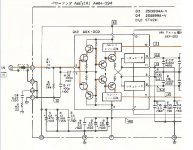
For years me and the world have been under the impression that comlinear was the developer of the famous CFB topology that uses the diamond buffer as input. They also were the first to patent it in 1985 if Im correct and hold more than 20 other patents regarding CFBs.
Yesterday I got proof of what I have been was suspecting for a while now, a Japanese company had a amp on sale in 1980 with that topology and quite surprisingly very advanced form of that topology. Take about two years for development and production and Id guess the topology dates from about 1977. This company is Pioneer. One has to wonder where comlinear got the idea whether themselves or ...... In those days circuit topologies were a sacred secret in japan and its very difficult to find schematics of their amps which were sold only in their homeland.
Here is a preview although I hope to get the rest of the schematic into electronic form.
Attachments
There were many VFB amps simulation with THD20k in ppm or sub ppm range(Edmond's is one of them)) presented here, but I never saw CFB simulation here in that distortion level, so maybe you could present such simulation. What you mean by "better specification", it could be many things?
dado
Just look at the CFB opamps by National
- Status
- This old topic is closed. If you want to reopen this topic, contact a moderator using the "Report Post" button.
- Home
- Amplifiers
- Solid State
- Is the CFB topology superior, and why?