All you need to do Jay is to look up the course material for electronics that is taught in every tertiary institution on the planet, I have, and that is what it says, and if it doesn't match your prejudices well I am sorry but science is like that.
Don't shoot the messenger if you don't like the message is all that I can say, and I am just the messenger.
rcw
Don't shoot the messenger if you don't like the message is all that I can say, and I am just the messenger.
rcw
All you need to do Jay is to look up the course material for electronics that is taught in every tertiary institution on the planet, I have, and that is what it says, and if it doesn't match your prejudices well I am sorry but science is like that.
Don't shoot the messenger if you don't like the message is all that I can say, and I am just the messenger.
rcw
No, I'm not shooting you the messenger. It is not that I don't like the message either. I want complete answer, technical justification from your side, not the basics we all know. Of course, not everyone can think of complex things. For example, go in detail with what you think is a misconception. Or, explain about inter-modulation and other issues, show that every aspects have nothing to do with high slew rate or anything.
It is a nature of intelligent people to look beyond the normal boundaries. Sometimes, it is just a kind of intuition (which is of course impossible without underlying theories). Slew Rate = frequency times 2pi times Vpeak is nothing. It is too basic to be considered as "technical justification". You shoot others by saying they have assertions with not good enough justifications. I think they have already one or a few steps above accepting the basics/standards. And that really help people like me to find the justification itself. I want the "answer", and I feel that I can get the answer from/through people who can think beyond the normal boundaries.
I have no conclusions ready. I am freely reflecting on the subject, and I am sharing my thoughts.
I think there are a number of misconceptions about all this: firstly, in actual circuits the difference between the two is not as clear cut as many would like to believe, and secondly the virtues or flaws attributed to one or the other seem to disappear as soon as you normalize the conditions of the comparisons.
Bigun's opinion looks convergent with mine.
My opinion is that they are apple and orange. Like solid state versus tubes, like mosfet versus bipolar. Each has their own characteristics. It is a bit impossible for me to "compare" a bipolar to a mosfet to find out which one is superior. Because no one is superior than the other.
My interest is to compare the best implementation of CFB, and the best implementation of VFB for audio listening purposes.
I think CFB noise cause is dominate by current, not voltage as in VFB. This means that for a high power amp where (voltage) gain is high, (noise) performance at high power is optimal with CFB.
I don't know if F5 is CFB or VFB (and that's not my interest to know the difference), but I found that similar topology TSSA has preferable performance at high power. F5 is only good at first watts, driving high sensitivity drivers. At high power, F5 and F5 Turbo is less suitable than a TSSA.
All you need to do Jay is to look up the course material for electronics that is taught in every tertiary institution on the planet, I have, and that is what it says, and if it doesn't match your prejudices well I am sorry but science is like that.
I tried to solve this by just looking it up, but I didn't get far.
Both Self and Cordell deal extensively with slew rate, generally in the terms expressed by rcw666, i.e. the slew rate necessitated by an amplifiers maximum power output at its highest frequency (20kHz). Self devotes some pages to methods of altering the slew rate.
Cordell, however, goes on to say this:- 'In practice a much larger value is required for low-distortion performance on high-frequency program content.'
He doesn't go on to justify this, however.
I thought initially that a simple way to get some answers as far as HF distortion is concerned, would be to set up an LTSpice sim of a conventional amplifier with global NFB, set it up to calculate THD20, and then fiddle with the Miller compensation cap to first set the slew rate to and then to increase it to above the value predicted as necessary by the max. slew rate required at a given 20kHz output amplitude, and see if it affects the THD20.
Unfortunately however, on reflection, the Miller compensation acts to linearise the VAS through local feedback, which has its own effect on the distortion performance. This interaction means that although the slew rate is affected by the Miller compensation, modifying it isn't going to show the effect (if any) of slew rate on HF distortion in isolation.
Perhaps someone else has some idea how to analyse this?
I do think, Jay, that it is really incumbent on you to 'show that every aspects have' something 'to do with high slew rate or anything'.
I am afraid Jay that it is you who need to supply justification for your assertions, I already have supplied the facts as they are recognised by every authority on the planet, and that is that a pre-amp needs a slew rate of note more than around .5V/us. to cover the audio band and op amps such as the 5534 cover this requirement more than adequately and are still the industry standard because of this and other factors, another of which is much greater flexibility of feedback arrangements over CFB types.
The basic fact about the CFB topology is that it allows greater bandwidth with a fixed internal pole splitting capacitor, and the advantage this occurs at frequencies that are far above the audio band. Why one would use such a device that has the basic disadvantage that it has very restricted configurations that can be used for feedback to gain a benefit which is of no use at all in a particular application I am not sure.
It is you who needs to tell us why it is better to do this, so please do so, giving actual technical reasons rather than just bald assertions.
rcw
When you don't use any form of active feedback, then your slew doesn't need to be more than what's needed for the signal.
But when you use a feedback loop, you do want the output to settle fast on startup transients and any other transients caused by the signal-to-reproduce (harmonics). A high bandwidth achieves that. A high slewrate in this perspective is nothing but a derivative of the quest for bandwidth.
But when you use a feedback loop, you do want the output to settle fast on startup transients and any other transients caused by the signal-to-reproduce (harmonics). A high bandwidth achieves that. A high slewrate in this perspective is nothing but a derivative of the quest for bandwidth.
If you are talking about the so called TID then as Leach showed this is really a function of Gain bandwidth product.
His low TID power amplifiers had a GBP in the 8-10MHz. range and do does the 5534 type op amp, there is no need for any more than this, and people who claim there is can provide no technical reason for it other than some vague notion that more must be better.
in the end most people can't hear the difference between a 741 op amp and a 5534 one except for low level amplification in which the former is a lot noisier.
In forums such as this you of course get plenty who claim you can, but these assertions are based upon a lot of subjective assertions and not on double blind tests, and are thus of very dubious credibility.
rcw
If you are talking about the so called TID then as Leach showed this is really a function of Gain bandwidth product.
His low TID power amplifiers had a GBP in the 8-10MHz. range and do does the 5534 type op amp, there is no need for any more than this, and people who claim there is can provide no technical reason for it other than some vague notion that more must be better.
in the end most people can't hear the difference between a 741 op amp and a 5534 one except for low level amplification in which the former is a lot noisier.
Initially you had bold assertion that someone like Juma couldn't hear the difference between 741 and any of his pet op-amp. Now you add one exception. Funny thing is that you use the word "LOT" which implicitly means something obvious.
Do you know what is happening here? What you need is actually a few more practical experiences then may be you can at the end say with full certainty that YOU yourself can hear the difference so easily.
I know that there must be somebody else have higher intelligence than I am. I know that there are people who knows better than me. I know that there are people who can hear better than I do. I know that there are many things that I don't know. It is a skill that you seem don't have.
And don't try to be safe. Mention what is the limit of the frequency to be considered in audio. 20KHz? 8-10MHz? Nobody has ever said that more is better. There is always limit for everything. You just mention your number now, so we can compare with your number next year, and the next 5 year
")
I tried to solve this by just looking it up, but I didn't get far.
Both Self and Cordell deal extensively with slew rate, generally in the terms expressed by rcw666, i.e. the slew rate necessitated by an amplifiers maximum power output at its highest frequency (20kHz). Self devotes some pages to methods of altering the slew rate.
Cordell, however, goes on to say this:- 'In practice a much larger value is required for low-distortion performance on high-frequency program content.'
He doesn't go on to justify this, however.
I thought initially that a simple way to get some answers as far as HF distortion is concerned, would be to set up an LTSpice sim of a conventional amplifier with global NFB, set it up to calculate THD20, and then fiddle with the Miller compensation cap to first set the slew rate to and then to increase it to above the value predicted as necessary by the max. slew rate required at a given 20kHz output amplitude, and see if it affects the THD20.
Unfortunately however, on reflection, the Miller compensation acts to linearise the VAS through local feedback, which has its own effect on the distortion performance. This interaction means that although the slew rate is affected by the Miller compensation, modifying it isn't going to show the effect (if any) of slew rate on HF distortion in isolation.
Perhaps someone else has some idea how to analyse this?
I do think, Jay, that it is really incumbent on you to 'show that every aspects have' something 'to do with high slew rate or anything'.
One option here is to take a wide band closed loop amplifier (a good fast opamp will do) and feed this through a low pass filter. It's very easy ten to set the RC time constant and hence slew rate independent of the amplier and to test the results both subjectively and quantitively.
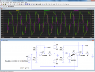
In theory, any CFB amplifier can be converted into a VFB one having at least identical performances.
Could you post a schematic, I dont believe this can happen, at least not at same operating conditions as I mentioned in previous post.
Here is conceptually how you go about it:Could you post a schematic, I dont believe this can happen, at least not at same operating conditions as I mentioned in previous post.
On the left is a normal CFB amplifier having a gain of 20dB.
The yellow trace is the output voltage, and the red one the input current: it is clearly a genuine current mode amplifier.
On the right is the same circuit, converted to VFB. The green trace has voluntarily been shifted by 0.5V, otherwise they are perfectly overlaid and undistinguishable.
To make the C to V conversion, the voltage on the (-) input has been isolated, buffered and applied to the (-) input via a resistor equal to the Thevenin resistance of the feedback network.
The circuit therefore operates perfectly identically to the first one, but there is obviously no current into point A: it has become a VFB.
Of course, in this case the operation is useless, but it was done on purpose to show the equivalence.
Morever, with an integrated amplifier like the LT1206, it makes little sense anyway, but in a discrete circuit, this gives you one more degree of freedom: you can free yourself if you want of the effect of the input current.
Some remarks:
This is conceptual, made with spice components. A real buffer would add some phase shift and some capacitance on the feedback node, but these are merely practical problems, and they are perfectly manageable.
Attachments
You might want to look at this if you haven't seen it already, from TI.
http://www.ti.com/lit/an/slva051/slva051.pdf
http://www.ti.com/lit/an/slva051/slva051.pdf
Last edited:
Name the advantages and disadvantages of VFB, Ill add the disadvantages youre not thinking of.
CFB outperformed all generations of VFB, even now the latest outperform the VFB if we look at opamps. Please name me one VFB opamp that could equal even the old 1980s comlinear opamps. Two gain stages ???, could you demonstrate.
Traditional VFB topology cant and never will reach the speed that can be attained by CFB, theory dictates. VFB can have larger slewrate at the cost of very high currents in the LTP, CFB on the other hand can probably reach 10 times that high if the same current is used.
Apart from slew rate a CFB is no better than a VFB and usualy
not as good in matter of linearity contrary to your sayings
wich was the point that i didnt agree with.
Indeed , the best opamps in this matter are VFBs.
As for high slew rate, it is pointeless if linearity is worse ,
wich is often the case with CFBs.
Last edited:
voltage primary current secondary does not matter where voltage is taken from directly from an output or from a sense resistor
audio amps without global feedback sounds much much much better to my ears
the reason is feedback has no clue if it is timbre of instrument or a power supply noise that NFB is currently suppressing
audio amps without global feedback sounds much much much better to my ears
the reason is feedback has no clue if it is timbre of instrument or a power supply noise that NFB is currently suppressing
Actually, feedback does have a clue, which is why it works.the reason is feedback has no clue if it is timbre of instrument or a power supply noise that NFB is currently suppressing
If it had no clue, the amplifier would be dead silent for noise, ripple, distortion ... and music.
Effective, but maybe a little too radical.
If you do hear a timberal difference with a no global feedback amplifier it is then you are hearing distortion added to the signal.
That the evil global feedback masks things that are magically revealed by its removal is nonsense, it removes things that amplifiers being inherently imperfect devices add.
As I have pointed out local only feedback is used when the frequencies to be amplified become such that the in and output parameters of the individual active devices start to become significant, and they don't even approach this condition for audio signals.
rcw.
Well I am just sharing my own preferences (I am more of audiophile than an engineer when it is related to music and do trust my ears always since it is just a hobby. Owned Carvers, Nakamichis, Accuphases and KRELL FBP behemonsters coupled to full sized Magneplanars before switching to no global NFB topology & back loaded horns. Studied Heaviside and Laplace transform at institute but many-many years ago so no mathematical proofs just like vivid or distorted sound without NFB a bit more. Had sacrificed my beloved Magnepans for that purpose. Some amps have switch NFB on-off BTW.)
On local country forum read that current sense resistor for NFB topology works very nice with full ranger speakers. It was somehow related to speaker crossovers that CFB might interfere with otherwise. Not sure if it is true or not just a possible aspect to consider maybe.
On local country forum read that current sense resistor for NFB topology works very nice with full ranger speakers. It was somehow related to speaker crossovers that CFB might interfere with otherwise. Not sure if it is true or not just a possible aspect to consider maybe.
One option here is to take a wide band closed loop amplifier (a good fast opamp will do) and feed this through a low pass filter. It's very easy ten to set the RC time constant and hence slew rate independent of the amplier and to test the results both subjectively and quantitively.
No. The question is whether otherwise identical amplifiers with different slew rates produce greater or lesser HF distortion when the global NFB loop is closed. It's fairly obvious that a LP filter following the amplifier might have no effect on a 20kHz fundamental but might still affect harmonics (regardless of whether inside or outside the GNFB loop) particularly if it has a steep rolloff, contributing to an excessively optimistic evaluation of performance.
It certainly seems intuitively that a higher slew rate indicates a higher BW and hence provides correction at higher frequencies when a feedback loop is closed around the amplifier. Many things in electronics are counter-intuitive, however.
It's common to observe that THD @ 20kHz can be expected to greater than that @ 1kHz because gain in a conventionally compensated amplifier is rolled of at 6dB per octave by Cdom and there is consequently less feedback to provide correction.
Slew rate and bandwidth, however are only indirectly related. Slew rate impacts directly on FULL-POWER bandwidth, but harmonics are typically 10's of dB down on the fundamental, and their rise-times are consequently considerably less.
Later in Bob Cordell's book we find:
Recommended Amplifier Slew Rate
The maximum slew rate from a CD source is limited by the very steep anti-alias filtering required by the Red Book standard for audio CDs. A square wave recorded on a CD will have a slew rate of about twice that of a 20-kHz sine wave of the same peak amplitude, or about 0.25 V/ms/Vpk. Newer recoding standards, like SACD and high-rate PCM, increase this maximum, at least in principle. Many amplifier input stages begin to exhibit nonlinearity well before slew rate limiting occurs. For these reasons, it is wise to have an amplifier slew rate that is about 10 times that of a full-amplitude 20-kHz sine wave. For a 100-W amplifier this corresponds to 50 V/ms. The minimum recommended slew rate for a 400-W amplifier is 100 V/ms. These numbers are not difficult to achieve in practice, given a sufficiently fast output stage.
This doesn't contradict the principle expressed by rcw666, but suggests that a more generous allowance might be advisable in practice.
Last edited:
It is true that current feedback is used to increase the output impedance of audio power amplifiers that are used with low Qt drivers, this increases the bass output, and is much used in guitar amplifiers and in bi-amped systems to drive low Qt compression drivers.
Many in diy audio look aghast at this because it removes the, "benefits" of high damping factor.
The use of current feedback is in this case one of semantics because the quantity fed back is a voltage that is proportional to the current in the load, and in what is known as the current feedback op-amp, there is a current fed back that is proportional to the voltage across the load.
The first type is then more correctly called a transconductance amplifier, or vccs, and the second sort a transresistance amplifier or a ccvs.
rcw
- Status
- This old topic is closed. If you want to reopen this topic, contact a moderator using the "Report Post" button.
- Home
- Amplifiers
- Solid State
- Is the CFB topology superior, and why?