Hi,
I googled to see if someone has already had this idea of the scheme. I have not found. (if someone knows, then I have not invented this) haha! Yesterday, after lunch, I made this amp (without PCB) in 15 minutes. for now, no comment but have measure eheh!
I googled to see if someone has already had this idea of the scheme. I have not found. (if someone knows, then I have not invented this) haha! Yesterday, after lunch, I made this amp (without PCB) in 15 minutes. for now, no comment but have measure eheh!
Attachments
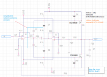
op-amp provides the voltage on the gate as needed, with sufficient current. Obviously this is very raw, just to test the concept. simplicity is shocking. All components remain cool, do not dissipate unnecessary power. i have tested also in class A range and with 300mA bias. it seem perfect.
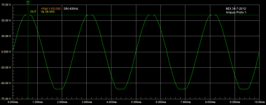
Since the concept is focused on the driver, this is the Vp on 8R (60V rail) I have no time now but I will try to complete this amp with other circuits, as protection etc..
d9-d10 not have sense in this circuit (only at start prevent gate) then i change with other solution.
d9-d10 not have sense in this circuit (only at start prevent gate) then i change with other solution.
Attachments
I want to clarify that this is not a super amp. may be of interest to educational level , considering ease. I have not tested all the parameters, just thd, frequency response. may perhaps be interesting to change the first-stage amplifier with an IC as TDA2030 (5 pin) and drive 4 for side mosfet for sub with a lot of power.
It's using opamps (with associated network) as "compound" input 'FET' differential pair. The nice thing about this is the programmable quite linieary inputstage gain which is defined by each opamp's local NFB. It should still be tons higher than the global feedback present so I'm guessing the FB ratio of each opamp is quite high. Using the output device's gain as a major gain component/voltage output it could be desirable to limit the input stage gain for sake of stability. The lineair programmable gain by this input stage seems to offer just that and it looks like it's a pretty stable circuit.
I would recommend using pairs for those output transistors when you want to output 180W /8 Ohm, 2 of each.
@Tekko: This is a nice example of what "wants" to happen in a circuit vs what "is" happening.
I would recommend using pairs for those output transistors when you want to output 180W /8 Ohm, 2 of each.
@Tekko: This is a nice example of what "wants" to happen in a circuit vs what "is" happening.
Last edited:
It's using opamps (with associated network) as "compound" input 'FET' differential pair. The nice thing about this is the programmable quite linieary inputstage gain which is defined by each opamp's local NFB. It should still be tons higher than the global feedback present so I'm guessing the FB ratio of each opamp is quite high. Using the output device's gain as a major gain component/voltage output it could be desirable to limit the input stage gain for sake of stability. The lineair programmable gain by this input stage seems to offer just that and it looks like it's a pretty stable circuit.
I would recommend using pairs for those output transistors when you want to output 180W /8 Ohm, 2 of each.
@Tekko: This is a nice example of what "wants" to happen in a circuit vs what "is" happening.
I totally agree with you, Also, this circuitry allows you to create an amplifier with very high slew rate, ultra low hysteresis considered that does not use a lot of bjt or MOSFET devices. I'll probably implementations for optimal performance with reduced cost and ease of development pcb. I would try a solution to 500Khz bandwidth and 2 mosfets per side, just for 200w at 8R. i have listen the first proto , is very fast, the sound seems good but I still do other measures extended to understand how far we can push and if it can be used commercially or share it with diy free project's.
-------------------------------------
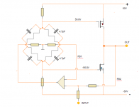
As you see, i have splitted in two section. one is voltage modulator, rest is bias/offset control, this allow use of low performances op-amp in this section. I think a base project (100Khz) can use one NE5534 with parallel 2 op-amp at input (it have gain compensation), and rest for bias/offest and protection.
Fig. 4 must be a simulation.
The RDS of the part at 25°C is on the order of 1Ω, so at 56V peak into an 8Ω load the voltage drop from Drain to Source will be on the order of 7V, thus requiring a regulated ±63V supply. After a few hundred milliseconds the RDS will go up to about 1.7Ω (according to the data sheet on the part).
The B&K ST140 ran on ±63V (brute force non-regulated supply) with one pair of these outputs and would do 115W/8Ω and 90W/4Ω (running at essentially maximum Id for the part).
The opamp/FET connection is like the front end of the old BGW and Crest amplifiers, both of which could sound good.
A builder might consider the Acoustat TNT method of driving ground with the FET pair, and having the speaker hot connected to the transformer center tap. The cases of the FETs would be at ground potential, eliminating the thermal resistance of an insulator. A good opamp could drive a double-die FET (16A/250W) pair and deliver 200W. IIRC you would need about 16mA drive current to drive the gate capacitance at100Khz for the double-die versions.
Both Exicon (ECF20N20A/ECF20P20A) and Magnatec (BUZ900D/905D) make the double-die devices.
Price
Quantity 1+ 10+ 20+ 100+
GBP £ 8.524 7.204 6.461 5.666
Last edited:
------------------------Fig. 4 must be a simulation.
The RDS of the part at 25°C is on the order of 1Ω, so at 56V peak into an 8Ω load the voltage drop from Drain to Source will be on the order of 7V, thus requiring a regulated ±63V supply. After a few hundred milliseconds the RDS will go up to about 1.7Ω (according to the data sheet on the part).
The B&K ST140 ran on ±63V (brute force non-regulated supply) with one pair of these outputs and would do 115W/8Ω and 90W/4Ω (running at essentially maximum Id for the part).
The opamp/FET connection is like the front end of the old BGW and Crest amplifiers, both of which could sound good.
A builder might consider the Acoustat TNT method of driving ground with the FET pair, and having the speaker hot connected to the transformer center tap. The cases of the FETs would be at ground potential, eliminating the thermal resistance of an insulator. A good opamp could drive a double-die FET (16A/250W) pair and deliver 200W. IIRC you would need about 16mA drive current to drive the gate capacitance at100Khz for the double-die versions.
Both Exicon (ECF20N20A/ECF20P20A) and Magnatec (BUZ900D/905D) make the double-die devices.
Price
Quantity 1+ 10+ 20+ 100+
GBP £ 8.524 7.204 6.461 5.666
I did not have available a pair of "ECX" mosfet in time of great curiosity to try, so I mounted an old pair of IRFP240/9240 with one DPS-600 at 63V. the rest is like the diagram. yes, I know you've listed mosfets, then we'll see. the crest with the same input / MOSFET connections, you are sure that the gate driver is in AC? (in this case therefore, requires a separate stage for the control of the bias / offset). just this concept that seems unique for me. Furthermore, this configuration allows to cancel the transverse current (used to obtain the bias) (which is dissipated by the driver in the traditional scheme, during normal operation (imbalance) of the final stage). This increases a few points for the total efficiency.
Last edited:
Hi,
After some reflections on this strange configuration , now everything is clear how it works.
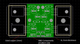
I decided to print the pcb, this circuitry is perfectly suited for a hybrid with aluminum base (with 4 mosfets mounted, two per side) that greatly facilitates the eventual installation of a heat sink. obvious that the hybrid is open (anyone can make it). I will make two models of this circuit. one 100Khz FR, and the other of 500Khz FR. although I have little time to devote to this amp, by some measures on the prototype, as the spectral purity and speed of execution, convinced me to continue.also, this scheme of connections is "magic" and is not possible change any things. it solve with only two active stage six functions,incluse input in phase with output.
Regards
After some reflections on this strange configuration , now everything is clear how it works.
I decided to print the pcb, this circuitry is perfectly suited for a hybrid with aluminum base (with 4 mosfets mounted, two per side) that greatly facilitates the eventual installation of a heat sink. obvious that the hybrid is open (anyone can make it). I will make two models of this circuit. one 100Khz FR, and the other of 500Khz FR. although I have little time to devote to this amp, by some measures on the prototype, as the spectral purity and speed of execution, convinced me to continue.also, this scheme of connections is "magic" and is not possible change any things. it solve with only two active stage six functions,incluse input in phase with output.
Regards
Attachments
- Status
- This old topic is closed. If you want to reopen this topic, contact a moderator using the "Report Post" button.
- Home
- Amplifiers
- Solid State
- Spirit of Amp