
There's so many NAD models, different design types and groupings, that we can't easily compare or evaluate them unless we have the model to hand or we're expert enough to understand what the designers intended from their topologies and component types/values.
I'm already at a disadvantage as I'm no expert and I haven't heard one in use but the 214 design has a CFA topology, regulated front end power supplies and an EF triple output stage with no tricks so I'd expect a very clean, low distortion sound with lots of grunt, as needed for bridged mode operation. There's a lot of capability and comprehensive protection there but not much is on offer for someone seeking audiophile quality sound. I can understand how a P3a, even the published website version we have all seen and copied, would beat this and many other, more expensive commercial models, on sound quality.
P3a may appear to contradict every current audio design maxim in its old school simplicity but that's where it's strong appeal as a DIY project and performer originate.
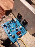
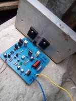
Long time ago I wanted to build this wonderful amplifier. I upload some photos of it..I
thank Stephie B., my friend, for helping me get original transistors for the input stage. Getting some old reciclying parts, at last! I finished the amp which differs from Rod Elliott's only by adding a current mirror to the differential pair collectors. I supplied the amp with +/-40, using C5200 and A1943 in the output stage, I left bias current at 30 mA for each transistor maybe bias is high but temperature through them kept normal. Rod does not recommend the Vbe multiplier is attached to the main heatsink since overcompesation can occur causing crossover distortion due to the complementary feedback pair or Sziklai pair used in the output stage. The sound is very good.
thank Stephie B., my friend, for helping me get original transistors for the input stage. Getting some old reciclying parts, at last! I finished the amp which differs from Rod Elliott's only by adding a current mirror to the differential pair collectors. I supplied the amp with +/-40, using C5200 and A1943 in the output stage, I left bias current at 30 mA for each transistor maybe bias is high but temperature through them kept normal. Rod does not recommend the Vbe multiplier is attached to the main heatsink since overcompesation can occur causing crossover distortion due to the complementary feedback pair or Sziklai pair used in the output stage. The sound is very good.
Attachments
I left bias current at 30 mA for each transistor maybe bias is high but temperature through them kept normal.
I think the recommended value is 50-70mA? Then 30mA is probably the minimum. If you think you need more current, you have to reduce the driver's collector resistors from the 220 Ohm, and prepare a small heatsink for the driver.
Hi johnego for your reply.. I think 70mA would be high enough to destroy the output transistors.
Mine is used daily and has been biased at 75mA for the last 5 years with 1943/5200 outputs. I would reduce to 2x35V though.
Hi johnego for your reply.. I think 70mA would be high enough to destroy the output transistors.
What do you think is the bias current of class A amplifiers? Mine is above 70mV across 0.47 Ohm output resistor. I think that's around 150mA?
Hi Jacques, but you measure bias current between collectors of both Power transistors?
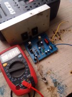
You can measure bias current in a number of ways.
1. use the amp reading of your PSU if it has one.
2. remove one fuse (see original schematics) and measure intensity across the fuse terminals with a multimeter.
3. Like Johnego suggested: read voltage across one of the output collector resistors and calculate intensity with Ohm's law.
Like 44250 said, the input must be grounded. The same thing I did, by applying Ohm's law.. I felt the heatsink got very hot when I fixed bias current at 50mA for each transistor.
Something must be wrong. This amp is designed for low bias current. Heat may come from oscillation.
Recommended bias (best sound quality) is a current around 70mA. If you read the early pages of the P3a comparison thread, you'll find that Sakis agreed with this too. The optimum, theoretical bias current for lowest THD is about 15mA, like most simple CFP output stages. Unfortunately, that setting isn't the most pleasant to listen to. Even 300 mA has been applied (with larger heatsinks) but higher increases like that don't appear to improve the sound any more.
Hi John, you speak about this amplifier is designed for Low bias current.. I think 30mA for each transistor is ok..
Yes 30mA is okay but there should be no heat with normal size of heatsink.
If you are used to listening to class A amps, the P3A is not for you or you have to modify it to allow for higher bias current.
If you increase bias without modification then you will get some benefits but lose some benefits too (here you should know/choose which you want better, impression or enjoyment) up to a point where crossover distortion is intolerable. To increase bias but to keep crossover distortion low you need to increase driver's current by lowering the 220 Ohm resistor at drivers' collectors. (drivers must have heatsink).
You should read Rod Elliott's recommendations on how to assemble, suitable power and cooling and to set up the amplifier as it was intended - which is about as good as it gets. There are many threads about P3a here that are mostly recycling the same design issues again and again for each new DIYer and copying only the basic schematic form you see at the ESP website. It is representative but not exactly the same, though people still like the results with the basic design. 60-80W Power Amplifier
- Home
- Amplifiers
- Solid State
- P3A-More upgrades