I have an old AP10P in a third system. I bought it back in the 90's so it has little intrinsic value. The AP10P is rated at 15W and I never expected it to rattle the walls, however I was musing the other day about "upgrading" it with a bigger power supply to give it a bit more grunt.
Currently it has an 18-0-18/30VA transformer feeding a 6A bridge rectifier and then 2 x 4700uF/35V caps to give +/- 25V rails. Output devices are BDV64A/65A using the 2mm aluminium floor panel (250mm x 200mm) as a heat sink.
As far as I can determine, the AP30 (30W) has the same output devices but a bigger power supply, namely a 25-0-25/100VA toroid and 4700uF/63V caps. So my thoughts are to replace the transformer, drop in a beefier bridge rectifier (25A) and replace the caps. A quick fiddle in Visio shows I can do this in its' current casework by rotating one of the amp boards.
I'd also need to change a few electrolytics rated at 25V on the amp boards and maybe tweak the "power" LED ballast resistor. Am I being too simplistic in thinking this is all it takes, or is there more to consider? Would I be changing the gain of the amp and therefore need to think about the value of the feedback resistor (3K83 on the AP10P, 18K on a bigger AP70, can't find a value for the AP30).
Thanks,
Duncan
You will be asking all the components on the pcb to handle more power /voltage , especially the semiconductors and you need to know if they will handle it .
To make the amp output 30W for the same input level you will need to increase its gain by 3dB . Increasing the rail voltages increases the open loop gain and not the gain set by the feedback resistors.
To make the amp output 30W for the same input level you will need to increase its gain by 3dB . Increasing the rail voltages increases the open loop gain and not the gain set by the feedback resistors.
No, you shouldn't need to mess about with the gain. It will almost certainly be set at 26dB. In fact I should say absolutely don't! The only thing limiting its power is the fact that there is a limit on the voltage on the rails. And with the tiny voltages you are looking at, upping things a bit should be well within the capabilities of all the devices on there.
Having said that, I wouldn't go as high as a 25V transformer as you may end up getting 38 or 39V out of it because they are designed for 220V supplies and we are largely on 240V still. A 22V would keep you safe, though if it is as weedy as 100VA, it'll probably sag enough to keep you clear of danger.
Finally you will almost certainly have to beef up the heatsinks, unless they are very over-specced. The output devices will be dissipating a lot more than they were with just 25V across them.
Incidentally, if you do get too high a voltage, one way of dropping it is to use two bridge rectifiers. It's an improvement anyway, but it should slough off another 1.5V or so.
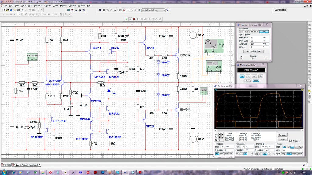
Here is a schematic of a larger NVA power amp, the A70, that I found on a Russian website. The only difference between that and the AP10P that I'm working on, apart from a cermet pot volume control, is that the AP10P has a 3K83 RC55Y resistor in the feedback loop whereas the A70 has an 18K resistor. All other passives and semis are identical.
From that I would infer (maybe incorrectly") ) that the only difference as you move up the NVA range is a) bigger power supplies and b) increased gain by reduced feedback? So having transplanted the equivalent PSU (100VA from 30VA) of the AP20 amp into my AP10P, can I up the gain by playing around with the feedback resistor value? Maybe 6K?
) that the only difference as you move up the NVA range is a) bigger power supplies and b) increased gain by reduced feedback? So having transplanted the equivalent PSU (100VA from 30VA) of the AP20 amp into my AP10P, can I up the gain by playing around with the feedback resistor value? Maybe 6K?
From that I would infer (maybe incorrectly
) that the only difference as you move up the NVA range is a) bigger power supplies and b) increased gain by reduced feedback? So having transplanted the equivalent PSU (100VA from 30VA) of the AP20 amp into my AP10P, can I up the gain by playing around with the feedback resistor value? Maybe 6K?
I've ended up with a 24V/100VA from RS.Having said that, I wouldn't go as high as a 25V transformer as you may end up getting 38 or 39V out of it because they are designed for 220V supplies and we are largely on 240V still. A 22V would keep you safe, though if it is as weedy as 100VA, it'll probably sag enough to keep you clear of danger.
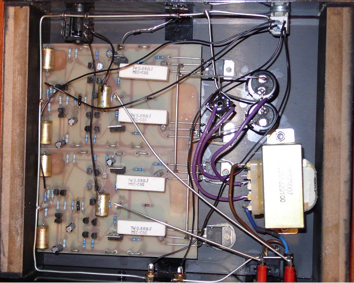
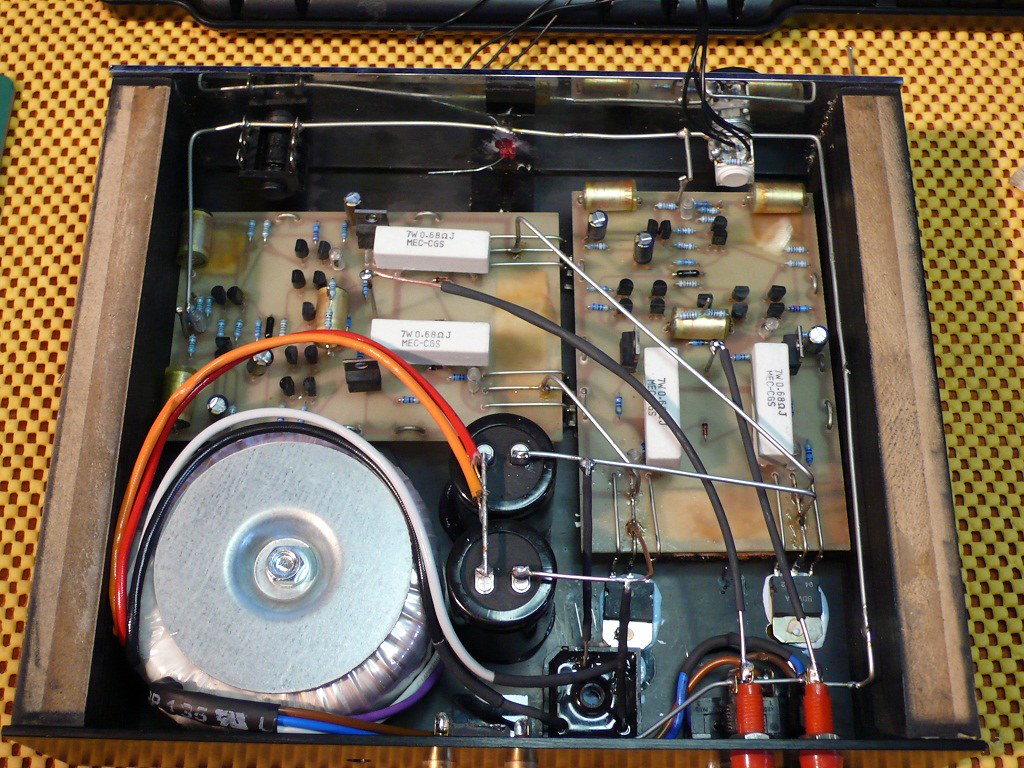
The output devices are thermally bonded to the 2mm aluminium floor of the enclosure as this picture shows. Approx 500 cm sq of heatsink.Finally you will almost certainly have to beef up the heatsinks, unless they are very over-specced. The output devices will be dissipating a lot more than they were with just 25V across them.
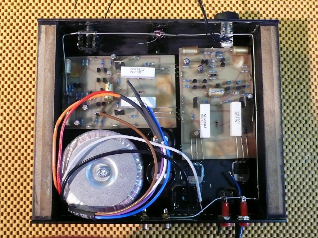
Here's where I am at the moment. One of the amp boarsd has been relocated to make way for the transformer. The ground bus running round the outside has been rerouted the other way round the enclosure, again to make way for the transformer. The new reservoir caps are in place and the new rectifier is thermally bonded to the floor pan, not floating in mid air as it was before. Final job is to wire it all up.
Regarding the feedback resistor and gain. You can see the black Welwyn RC55Y resistor mid board between the two ranks of small transistors. A closer inspection shows it is mounted on pins. So again this leads me to ponder if the boards are made "in bulk" and a specific feedback resistor, dependent on final application, is mounted. Although why you wouldn't just solder the one required through board eludes me.
Regarding the feedback resistor and gain. You can see the black Welwyn RC55Y resistor mid board between the two ranks of small transistors. A closer inspection shows it is mounted on pins. So again this leads me to ponder if the boards are made "in bulk" and a specific feedback resistor, dependent on final application, is mounted. Although why you wouldn't just solder the one required through board eludes me.
Crikey, is that what they look like?
Is that hot melt glue I see? I doubt it is either the right thing or that it will hold up if it is. An epoxy maybe, but I'd go for screws, mica and paste - doubtless they have to be non-magnetic! <g>
Changing the gain is very odd. And to be so different. Apologies to the other contributor who must know more about NVAs than I do. Another RCY55 is probably a good idea. But whether you need to depends on how much your pre amp will kick out. I'd try it first. But 6k would seem to be a good enough compromise.
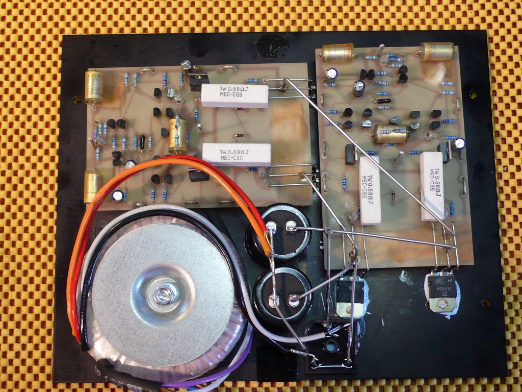
Yup. They're fairly simply put together. The amp boards are glued onto wooden blocks which again are glued onto the base. The reservoir caps are glued to the base and the output drivers thermally bonded to the base - insulating epoxy with thermal paste (e.g. RS 155-8320). All the buses and +ve/-ve feeds are breadboarded with 1.4mm wire. Sounds odd, but it is extremely rigid.
I've done the same with my rebuild, just two changes. I've thermally bonded the bigger rectifier to the base as well as the relocated output devices, but mounted the caps with silicone. Here's how it looks now. I just need to hook up the ground, inputs and outputs and see what we have!
I've done the same with my rebuild, just two changes. I've thermally bonded the bigger rectifier to the base as well as the relocated output devices, but mounted the caps with silicone. Here's how it looks now. I just need to hook up the ground, inputs and outputs and see what we have!
Last edited:
Christian,An epoxy maybe, but I'd go for screws, mica and paste - doubtless they have to be non-magnetic!.
I just noticed this bit. The designer of the amps is very much into "non-magnetic" which is why the case has only four screws, wooden cheeks and the top panel is held on with double sided tape! I suspect his thoughts in that area also influence the choice of fastenings used elsewhere, e.g. wood glue, and thermal epoxy paste.
Duncan
All done. The original wire is all uninsulated but very thick (c. 1.5mm) and therefore the whole "loom" is very rigid. However after the re-build I've added a bit of heatshrink on the rectifier legs and the outputs just in case.

Final steps were to connect up the ground bus and run the signal wires.
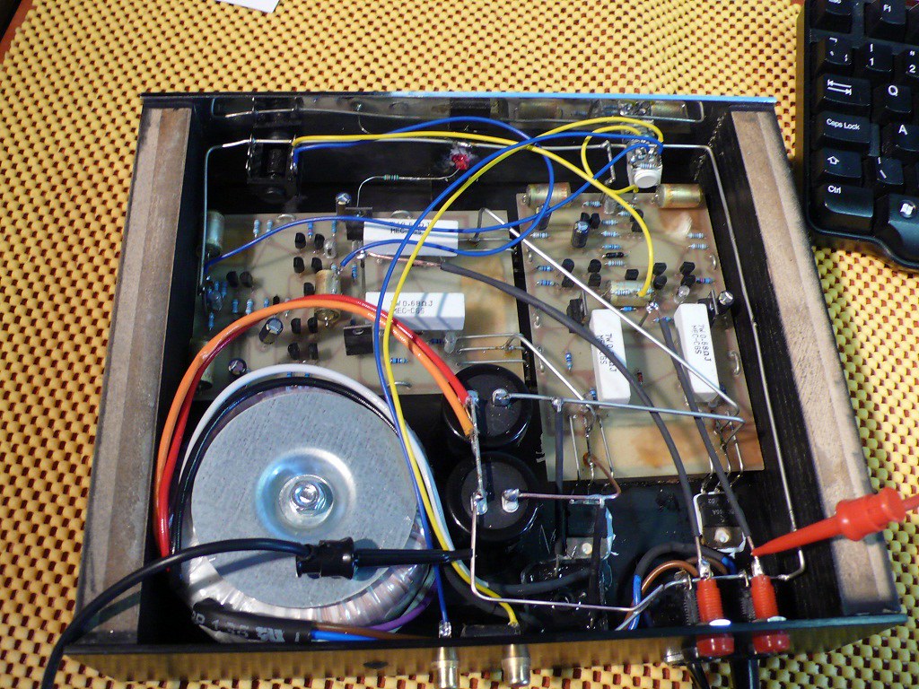
I powered it up and, miraculously, no magic smoke! DC offsets look good and everything is cool. Just a bit of warmth in the TIP31A/32A pre-drivers, but these are TO220 for a reason I guess. I'll let it burn in and see how that goes before I connect anything up to it.
Final steps were to connect up the ground bus and run the signal wires.
I powered it up and, miraculously, no magic smoke! DC offsets look good and everything is cool. Just a bit of warmth in the TIP31A/32A pre-drivers, but these are TO220 for a reason I guess. I'll let it burn in and see how that goes before I connect anything up to it.
I have worked out the original input sensitivity to be 1.197V for 15W output with a gain of 19.22dB . If you dont alter the gain you will now need 1.693V for 30W output.....most likely not a problem.
If you want to restore the sensitivity change the feedback resistor from 3K83 to 5K6 which would give a new gain of 22.22dB
The original amp appears to be double insulated (provided im not missing anything ) . Please made sure your new transformer installation complies with this or install a safety earth ( for yours and others safety ).
Thanks Epi, I'll try that value and report back.I have worked out the original input sensitivity to be 1.197V for 15W output with a gain of 19.22dB . If you dont alter the gain you will now need 1.693V for 30W output.....most likely not a problem.
If you want to restore the sensitivity change the feedback resistor from 3K83 to 5K6 which would give a new gain of 22.22dB
The amp has no "double box" logo, but it is missing an earth. It dates from c. 1993 so maybe the rules were less stringent then? The toroid I'm using is one of these. It suggests compliance with all sorts of regs and is stated to be a "safety isolating transformer". Would that qualify it as a component in a true double insulated installation?The original amp appears to be double insulated (provided im not missing anything ) . Please made sure your new transformer installation complies with this or install a safety earth ( for yours and others safety ).
The resistors are 1K0.What are the values of resistors for headphone output? These two pieces soldered to the capacitor, which is located in the middle of the PCB.
+/- 37.55V.What voltage did you end up with as a matter of interest?
NVA are still going strong, but primarily a word-of-mouth and eBay business. This is their eBay shop.Thanks for the schematic - and the infos about the gain differences. I was not aware about that. Any info about these amps is interesting for me, I remember they were fairly good. Isn't the NVA still in business somehow (maybe under a different name)?
I've had this playing/soaking all day and there's certainly no clipping that I was seeing at full volume before; with only 15W it's tempting to crank the volume all the way up. I fancy a few more watts so I'll try the 5K6 feedback resistors to see where this leads. Even running for hours at full chat, the base plate/heat sink gets only mildly warm to the touch.
the most serious problem with these amps is thermal compensation , beyond that the choice of outputs is even more horrible ...i am truly surprised to listen that someone thinks that a "thing" like that can play music BDV 66-67 are only good for solenoid drivers or relay drivers .
add to the above that there is absolutely no input filtering no input capacitor ( can be tricky ) and for every output transistor there is 470nf miller or stabilizer capacitors that between amplifier people are notorious as ...sonic killers ....
thermal run away, with poor heatsink ,no ventilation ,absence of fuse ,poor choice of output devices no thermal compensation, and higher rail voltage is a bomb construction
all family of darlingtons BDV66-67 TIP 142-147 BDW 83-84 will suffer from thermal runaway even if a proper VBE multiplier exists on the circuit if the amp is pushed ....imagine how is going to be without it
smoky regards
sakis
Last edited:
here is pictures of bigger NVA ..toasted cause the user wanted to make a ""burn in "" to his brand new speakers and he thought that was ok to keep the amplifier working with music to a modest level of 30% for a period of 24 hours .
amplifier boards completely toasted
both of main power transformers toasted ( since the amp had no fuse )
both woofers toasted
a total damage over 2.000 euro ..as about the construction i see it as a total mess with or without the telephone cables .....Obviously not a device that you are supposed to pay almost 1000 euro ...that is a ripoff


- Status
- This old topic is closed. If you want to reopen this topic, contact a moderator using the "Report Post" button.
- Home
- Amplifiers
- Solid State
- Beefing up an NVA AP10P Amp