Although I've just joined the forum I've dabbled in DIY for a number of years - thought I would share with you the balanced FET amplifier that I designed and built about 10 years ago, and have been using ever since. My major goal in this exercise was to build something that works, using the minimum number of components. Well it certainly works, after 10 years of hard use I've blown up a few diode bridges, but that has been solved with a bigger heatsink. Otherwise - flawless operation! But does it work well? Ok it sounds good to me, 2 of my mates have built there own models so that is a vote of confidence.
Key features of amp are:
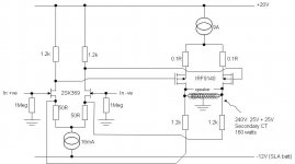
- balanced input and output
- only 2 stages, all FET (output is common source mode)
- output is choke loaded. I used the 2 secondaries on a 240V:25V + 25V toroid, bought off the shelf at a local electronics store. Though sold as a power transformer and no pretensions as an audio transformer, it works very well. Each secondary measures about 220mH.
- Output could be something around 40 watts class A, but never tested it. There are BIG heat sinks for the 9A current sources, and big heat sinks for the output FETs.
- Given limited output, I have built 2 "stereo blocks", one stereo block for each speaker in bi-amp mode. My tweeter is more sensitive than the bass driver so I have reduced the feedback resistors in the tweeter amps (ie more feedback, less gain) to match levels.
- Positive rail is provided by a choke input p-s. Choke is 6mH at 10A. One power supply for each channel (ie 4 power supplies).
Hmm that's about it.
Key features of amp are:
- balanced input and output
- only 2 stages, all FET (output is common source mode)
- output is choke loaded. I used the 2 secondaries on a 240V:25V + 25V toroid, bought off the shelf at a local electronics store. Though sold as a power transformer and no pretensions as an audio transformer, it works very well. Each secondary measures about 220mH.
- Output could be something around 40 watts class A, but never tested it. There are BIG heat sinks for the 9A current sources, and big heat sinks for the output FETs.
- Given limited output, I have built 2 "stereo blocks", one stereo block for each speaker in bi-amp mode. My tweeter is more sensitive than the bass driver so I have reduced the feedback resistors in the tweeter amps (ie more feedback, less gain) to match levels.
- Positive rail is provided by a choke input p-s. Choke is 6mH at 10A. One power supply for each channel (ie 4 power supplies).
Hmm that's about it.
Attachments
With 20v rails maximum output into 8 ohms is about 24 watts. Actual will be lower due to losses and series impedances/resistances.
What is ur 9A current source?
That is really a lot of current... do you have 4 ohm or lower Z speakers?
About 3.5a is all that is needed usually...
Big heatsinks?
Got pix??
Fun design.
_-_-bear
What is ur 9A current source?
That is really a lot of current... do you have 4 ohm or lower Z speakers?
About 3.5a is all that is needed usually...
Big heatsinks?
Got pix??
Fun design.
_-_-bear
G'day hazard500. Several years ago I played around with an amplifier that is an extension of your idea. It had a second identical winding on the same core that went from source to source and the centre tap went to +V. The phasing is opposite to the bottom winding and there is a large electro from each source to the opposite side drain. Voltage gain of the output stage is x2 which is a bit lower than yours but the advantage is that the transformer has virtually so effect on the sound quality because the signal does not need to go through the core, it goes through the cross-connected electros. See what you think. --> http://www.diyaudio.com/forums/solid-state/10658-tetrahedron-output-stage-topology.html
Wow. 4.5A per side in the output stage. That thing is a monster!
OK so first thing is that my speakers are 4 ohm load. Bass driver is 2 * Magneplanar tympany panels in parallel (each measures 8 ohms). Tweeter is a Bohland Graebner RG75 ribbon, also 4 ohm. So impedance is halved, output power is doubled. And since this is fully balanced, voltage swing is doubled, which gives additional power - but you need more current.With 20v rails maximum output into 8 ohms is about 24 watts. Actual will be lower due to losses and series impedances/resistances.
What is ur 9A current source?
That is really a lot of current... do you have 4 ohm or lower Z speakers?
About 3.5a is all that is needed usually...
Big heatsinks?
Got pix??
Fun design.
_-_-bear
Bear - your calculation above is correct for a single end push pull circuit (eg conventional power amp topology with symetrical output stage). In my case, I'm using balanced push pull. As my speaker is 4 ohm, each amplifying device is effectively driving a 2 ohm impedance - the speaker, which is across the oputput inductor could be replaced by 2, 2 ohm speakers with a ground point at the centre tap (this is why the current is so big). So if each output device is to drive (say) 25watts into 2 ohms then Vrms = 7 volts, V peak = 10V. I have a V peak of 20 volts, but I lose at least 5 volts in the current source But still at least 10V available). And of course I only need one voltage rail, because the inductor "provides" the opposite rail. And still into a 2 ohm load @ 25 watts, Irms = 3.5A, Ipeak = 4.9A. I've only specified 4.5 A, so I'm a bit shy on current, so ignoring losses will get 20watts per device, or 40 watts total - all class A as it can't go into class B. And as I bi-amp, that's 40 watts for the woofer, 40 watts for the tweeter.
9 amp current source is a "ring of two" with a small bjt as the voltage controller, and a IRF9140 handling the current. Nicked this part of the circuit from Nelson Pass. Big heatsinks, yes! Will take a picture on the weekend.
Thanks for this. Your original post says that the point of the circlotron is to enable use of same polarity devices in the output, and that is exactly what i was aiming for as well. However I have achieved this with one power supply rather than 2 so I consider this a plus.G'day hazard500. Several years ago I played around with an amplifier that is an extension of your idea. It had a second identical winding on the same core that went from source to source and the centre tap went to +V. The phasing is opposite to the bottom winding and there is a large electro from each source to the opposite side drain. Voltage gain of the output stage is x2 which is a bit lower than yours but the advantage is that the transformer has virtually so effect on the sound quality because the signal does not need to go through the core, it goes through the cross-connected electros. See what you think. --> http://www.diyaudio.com/forums/solid-state/10658-tetrahedron-output-stage-topology.html
I need to read more thoroughly your explanation of the circuit, I've read Broskie as well and circlotrons still make my head spin a bit. But you also need to consider, I have designed a complete amp, a circlotron is just an output stage. Not sure why you get a voltage gain of 2, if you have balanced inputs then voltage gain only equals 1? I am guessing that voltage gain of 2 assumes that you start with a single end signal, and then invert phase to drive the other input. But have you got a complete circuit?
Cirlotron, I've had a another look at this link, and the link contained within it, and realised (remembered) where I got the inspiration for the output stage of my amp - it is a copy of the output stage of the Richard Burfoot amp from WW Nov '99.G'day hazard500. See what you think. --> http://www.diyaudio.com/forums/solid-state/10658-tetrahedron-output-stage-topology.html
http://www.diyaudio.com/forums/solid-state/8725-inductance-loaded-current-amplifier.html
I now remember that I was originally inspired by a single end fet amp that was published by Hi Fi World in the mid '90s, I was keen to build one but couldn't find an appropriate choke anywhere. But the Burfoot output stage was much easier as all it needed was a common, garden variety power toroid. From there it was a simple step to mirror the single end amp into a fully balanced design so i could actually use the toroid. If I recall, the Burfoot amp claimed 48watt output from 12 volt rail. My first prototype actually followed his topology (notice that it doesn't have a current source in the output LTP) and I powered it from a 12V car battery - sounded good for about 2 hours untilthe battery went dead. Clearly it was not sensible to run an amp consuming 9 amps from a battery so I built a power supply and also added the current source to the output stage LTP.
So there is nothing new under the sun. All this was a long time ago. I just listen to it these days, driving kids around all weekend to various sports and social activities keeps me away from the soldering iron.
The outputs on mine are source followers so the output swing of each mosfet impressed across half the transformer winding is about equal to the gate drive but the load is across the entire winding so it gets twice the voltage, hence the x2 gain. But you could counter that by saying the gain is only x1 by comparison to the differential drive voltage.Not sure why you get a voltage gain of 2,
Mine also has 1 power supply, the cross-connected electros doubling as filter caps.However I have achieved this with one power supply rather than 2 so I consider this a plus.
Although I've just joined the forum I've dabbled in DIY for a number of years - thought I would share with you the balanced FET amplifier that I designed and built about 10 years ago, and have been using ever since.
You can improve the efficiency of your amplifier by harmonising the supply voltage/current.
I agree with your guess of about 40W output. However, the amplifier topology you show has a nominal efficiency of 50% so, with a supply voltage of 20V and bias (quiescent) current of 9A as shown, you should be expecting 20x9/2 = 90W - more than twice what you are actualy getting.
There are 3 basic options: a) change the bias current b) change the speaker impedance or c) change the supply voltage.
a) would mean increasing the bias current to 20A, this would raise the output power to 200W but would introduce lots of other problems.
b) would mean increasing the speaker impedance to 8.89 ohms, this increases the output power to 90W but is realy not practical though 8 ohms would be a lot better than the 4 ohms you are using - almost doubling the output for free.
c) would mean reducing the supply voltage to 9V and would be my choice. The output power will then be 4 x 9V^2 / 8 x 4 ohm = 40.5W and the input power will be 9V x 9A = 81W giving n = 50% which is correct for this topology. This keeps the power the same but drops the input power to less than half what it is now.
I see you are using source resistors, for dc stability I'd guess, these will of course reduce both power and efficiency slightly as will Rds and the inductor resistance of course but probably not noticably.
I bet it sounds nice though doesn't it?
- Status
- This old topic is closed. If you want to reopen this topic, contact a moderator using the "Report Post" button.
- Home
- Amplifiers
- Solid State
- balanced class A fet amplifier