I am not sure fast fuses could deal with the on rush current this build has. There is one way to find out, just buy some fast blow and find out. What kind of soft start speaker protection are other members here are using for this amplifier? I know the store sells a board but I am interested in knowing alternatives.
Rail fuses are there to protect the power supply from a shorted wire or amplifier module (none are going to be fast enough to protect the output devices or speakers). Slow blow is better there. After full load testing the amp have a close look at the center of the fuse element for discolouration. If you see any the fuse was beginning to melt and needs to be larger. This shows up as "fuse distortion" on the audio output. It looks like clipping on a scope.
If you want a complete state of the art protection system that will protect the whole amplifier and your speakers have a look at this system Amp Control System V6.2.2 Boards Bundle (5 PCBs, Simpelstark family) – Virtual Zero Audio Store
How to build a 21st century protection board
If you want a complete state of the art protection system that will protect the whole amplifier and your speakers have a look at this system Amp Control System V6.2.2 Boards Bundle (5 PCBs, Simpelstark family) – Virtual Zero Audio Store
How to build a 21st century protection board
Rail fuses are there to protect the power supply from a shorted wire or amplifier module (none are going to be fast enough to protect the output devices or speakers). Slow blow is better there. After full load testing the amp have a close look at the center of the fuse element for discolouration. If you see any the fuse was beginning to melt and needs to be larger. This shows up as "fuse distortion" on the audio output. It looks like clipping on a scope.
If you want a complete state of the art protection system that will protect the whole amplifier and your speakers have a look at this system Amp Control System V6.2.2 Boards Bundle (5 PCBs, Simpelstark family) – Virtual Zero Audio Store
How to build a 21st century protection board
I can vouch for the 21st century protection board. I have a V5.3 with DC protection, thermal protection, soft start, over and under line voltage protection, overcurrent protection, and MOSFET power supply disconnects/protection. It's all ran by an Aurdino chip and is modifiable.
Hello Friends,
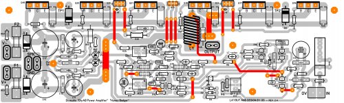
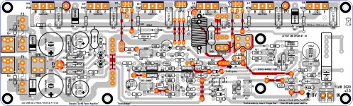
I am planning to make the Honey Badger. I could not find the version 2.4 layout here for the toner transfer method. Have seen the below Sprint file posted by Still4given. My question is, Is this a tested and working layout?. Please let me know if any one of you have already tried it.
Thanks
Sha
I am planning to make the Honey Badger. I could not find the version 2.4 layout here for the toner transfer method. Have seen the below Sprint file posted by Still4given. My question is, Is this a tested and working layout?. Please let me know if any one of you have already tried it.
Thanks
Sha
Thank you Juan for the quick reply ")
Yeah, these are the files which I am looking for and I can make the PCBs out of it through toner transfer.
But my worry is, is this layout tested by someone? please let me know.
Thanks again.
Regards
Sha
Yeah, these are the files which I am looking for and I can make the PCBs out of it through toner transfer.
But my worry is, is this layout tested by someone? please let me know.
Thanks again.
Regards
Sha
for what I see yes it should work for PDF transfer right?
Beautiful looking clone Great work!!
Could you please help me out to get the PDF of your clone for toner transfer.
Thank you.
Regards
Sha
Great work!! Could you please help me out to get the PDF of your clone for toner transfer.
Thank you.
Regards
Sha
should be okay to use that one is been tested check my clone PCB I just change one thing because it use to have an RCA and I removed because it cause a distortion on Mr. ST build
Thanks a lot Juan for this kind support . Respect the artist in you.
Regards
Sha
. Respect the artist in you.Regards
Sha
ok ok here is the same
Hi All,
I've made a few improvements to my amplifier including Mu-metal shielding, correct power supply snubber network using the Quasimodo, 240v mains line filter. While also improving my attenuator and measurement technique. I think this is as good as it gets for the HB using standard components. I'm now looking into measuring the loop gain so I can see what the phase and gain margins are.
Then I can look at decreasing the competition capacitors to get more loop gain which will give me more negative feedback which should result in lower levels of distortion.
Hello,
I am a new member and have joined to ask for help with an Amp Camp Amp build I just completed. MY let channel audio is very weak vs. the right. I notice that when turning on the amp I hear the caps of the right charge up but not the left. the bias on both channels is 24.3. I have checked solder joints and see no grounds and both boards are the same. the amp is set up as stereo so bridging is not an issue. I suspect one of the caps is the issue but do not have testing equipment to check. I did check all the resisters when I populated the boards and all were in spec.
Any advise would be help. I have built several tube amps and have had now problems but the built has me stumped.
Thanks,
Herb
I am a new member and have joined to ask for help with an Amp Camp Amp build I just completed.
Hi Herb
Welcome to diyAudio!
I'd suggest you post your question in the Amp Camp Amp thread here: Amp Camp Amp - ACA
- Home
- Amplifiers
- Solid State
- diyAB Amp The "Honey Badger" build thread