Distortion Measurements
Hi Guy's
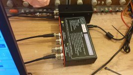
I just thought that I would share some information & photo's showing the distortion measurements of my Honey Badger using the QuantAsylum QA401.
I only received the QA401 last week, and so far, I'm very happy with its performance.
I initially ran some loop back tests and discovered that the lowest THD levels were achieved with a input level of -10dBV and the lowest THD+N levels were achieved with a input level of 0dBV.
I was able to see a loop back THD distortion of 0.00025% at -10dBV input level and a loop back THD+N distortion of 0.00090% at 0dBV input level.
So I decided to try and find a common input level where I could still achieve good loopback results. It turned out that -5dBV was the best choice.
At a input level of -5dBV I was able to achieve 0.00037% THD and 0.00082% THD+N respectively during a loopback test.
I then accurately measured the gain of the Honey Badger. In my case it was 28.52dB or 26.6667 AV.
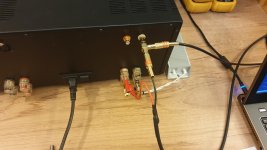
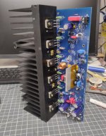
I wanted to test the amplifier at a medium power levels to begin with so I decided 80 WRMS into 8 ohms would be a good starting point. This equates to an output level of about 25.29V or about 28dBV. I also needed to make some type of attenuation circuit to drop that output level down to -5dBV so I could optimism the readings for the QA401.
This was done by making a L-Pad attenuation circuit. It's the little black box behind the QA401. I created a spreadsheet to do the calculations for me. See the attached zip file if your interested. In future I will install a 6 position switch with different attenuation levels so I can run a range of output levels and still have -5dBV input into the QA401
I then adjusted the Input gain level of the y-axis dBV scale on the QA401 so I could see the output power level on the display of the QA401.
The math to set the right level in the input box provided was 28.52 dB (from the Honey Badger) + 5.1 dB (which was the input level that I was getting without and input gain level adjustment due to my attenuation circuit) - 0.5dBV (which was the output level of the QA401 that I needed to achieve a output level from the Honey Badger of 28dBv or 80WRMS) this gave me a final value of 33.1dB
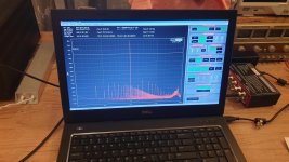
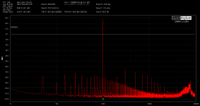
The results were very satisfying and a great starting point for further tweaking and measurement. I have attached a few images of my setup and the result plot.
I was able to achieve a reading of 0.00296% THD and 0.00374% THD+N.
To be honest I have no idea how to interpret the rest of the distortion levels and the harmonics caused by the 50Hz on the power supply.
Is this normal or is this an issue?
I would love to hear some feedback on this plot and what you guys think.
Cheers.
Hi Guy's
I just thought that I would share some information & photo's showing the distortion measurements of my Honey Badger using the QuantAsylum QA401.
I only received the QA401 last week, and so far, I'm very happy with its performance.
I initially ran some loop back tests and discovered that the lowest THD levels were achieved with a input level of -10dBV and the lowest THD+N levels were achieved with a input level of 0dBV.
I was able to see a loop back THD distortion of 0.00025% at -10dBV input level and a loop back THD+N distortion of 0.00090% at 0dBV input level.
So I decided to try and find a common input level where I could still achieve good loopback results. It turned out that -5dBV was the best choice.
At a input level of -5dBV I was able to achieve 0.00037% THD and 0.00082% THD+N respectively during a loopback test.
I then accurately measured the gain of the Honey Badger. In my case it was 28.52dB or 26.6667 AV.
I wanted to test the amplifier at a medium power levels to begin with so I decided 80 WRMS into 8 ohms would be a good starting point. This equates to an output level of about 25.29V or about 28dBV. I also needed to make some type of attenuation circuit to drop that output level down to -5dBV so I could optimism the readings for the QA401.
This was done by making a L-Pad attenuation circuit. It's the little black box behind the QA401. I created a spreadsheet to do the calculations for me. See the attached zip file if your interested. In future I will install a 6 position switch with different attenuation levels so I can run a range of output levels and still have -5dBV input into the QA401
I then adjusted the Input gain level of the y-axis dBV scale on the QA401 so I could see the output power level on the display of the QA401.
The math to set the right level in the input box provided was 28.52 dB (from the Honey Badger) + 5.1 dB (which was the input level that I was getting without and input gain level adjustment due to my attenuation circuit) - 0.5dBV (which was the output level of the QA401 that I needed to achieve a output level from the Honey Badger of 28dBv or 80WRMS) this gave me a final value of 33.1dB
The results were very satisfying and a great starting point for further tweaking and measurement. I have attached a few images of my setup and the result plot.
I was able to achieve a reading of 0.00296% THD and 0.00374% THD+N.
To be honest I have no idea how to interpret the rest of the distortion levels and the harmonics caused by the 50Hz on the power supply.
Is this normal or is this an issue?
I would love to hear some feedback on this plot and what you guys think.
Cheers.
Attachments
Last edited:
My amp went pop last night. I am assuming in the same manner as the other day, but this time I was around to witness it. It had been playing for hours, first, sound for a hockey game, and then about halfway in the 3rd album in a row it went pop. For the first couple of hours, I checked temperature, and it was slightly warm. Checked again a little while later, same. And it was sounding great.
Now that I think about it, I did hear a little bit of ringing in the higher freq piano not long before it went. I thought that was a little weird, because it definitely was not there earlier in the listening session. But flash pop it did, and one channel died. I powered the amp off, and it was HOT. Why would I have gotten the thermal runaway? All the transistors were firmly attached to the heatsink. So I don't think that was my issue this time, (or last time).
Amp setup and options;
I set bias v to 28mv across TP1 and TP2, and dc offset was between 1 and 2 mv for each channel from spk gnd to output. I was able to set the tail current to 3.75ma, and 8.25v across r14 per the build guide.
I am using transitional miller compensation, and have the cascode and current mirror voltage set using the luxman way with 22k resistor at r18 instead of the zener option. My input transistors are matched mpsa18 (thanks Longspeak). Output transistors are on semi from mouser, njw3281g, and njw1302g. The board that is giving me trouble is using drivers mje15032 and mje15033.
My understanding is that matched output transistors is not a big deal, as the emitter resistors compensate for mismatched hfe.
Could the heatsink be too small? And after 1.5 hours, its fine, but after 3 it's just not enough? Its a big heavy hunk of metal, and there are fans that run underneath pushing the warm air up and out of the chassis.
Does the ringing I noted later in the listening indicate oscillation? I would like to test for oscillation, I have an analog scope. I have googled how to test for oscillation, but most of the posts just say to look for oscillation, or look for fuzziness at the top of the waveform. Is it as simple as that? Feed it a 1000hz signal, and look at the peaks for fuzziness? Tray again at a variety of signal frequencies? Or is it more obvious than that? I don't have a suitable dummy load resistor to throw on the outputs. (will add to next mouser order though). Would love for this to be a learning moment, and really figure this out.
Last thought, I have not cleaned up and properly tied off my wiring yet, could the birds nest effect be creating some capacitance that leads to oscillation?
Thank you for your help.
Attachments
Looks like your using a zener in the photo that you attached.I am using transitional miller compensation, and have the cascode and current mirror voltage set using the luxman way with 22k resistor at r18 instead of the zener option.
I had oscillation due to R19 and the zener diode being to large a power rating.
Check out post 4132 and the follow-up posts by Harry and myself.
Last edited:
this amp did not use any form of SOA protection, this is my main beef with this amp, if i were the designer i would have included a SOA protection scheme....
having said this, it is up to the end user to take precautions, do not drive the amp to clipping where spurious oscillations can happen...
clipping with an actual music signal can happen even if the amp was not producing that many watts as in a sine wave...clipping levels with a sine or music can be the same....
Your heatsink is sufficient for more than typical listening levels. If it was not hot after 1.5hrs then it should not be too hot after 3hrs so most likely you got intermittent oscillation. If your amp did not oscillate from the beginning then instability is often caused by driving amp into clipping but if you have anti-clipping diode it should not be a problem. If amp is oscillating Zoebel resistor gets hot or even burns. Anyway, with good scope you should see even very high frequency oscillation but if it's intermittent then you won't see it straight away.
Anyway, the main question is what caused this problem and if your board and soldering are fine then some of your components are faulty - or just one. So before watching what happens on your scope think which of your HB components are likely to be of poor (EBay?) quality because in the end you will have to replace these.
cheers,
I was digging into it last night, and one channel setsup perfectly fine
The other, the bias drifts, either higher and higher (accelerates up) or when adjusting trim pot, drifts lower and lower until it gets to 2mv (right about the same as DC offset), it won't stabilize. It drifts either up or down. I threw another capacitor in there at c9, but that didn't solve the issue. I am thinking maybe I have a bad trim pot? DC offset is stable, power supply voltage is stable and ripple noise looks good. Tail current is also stable and in spec for both channels.
I'll toss a 400 ohm resistor in there tonight, see if that stabilizes bias, and if so, try to get one in there that gives me a decent stable bias voltage.
Sound approach?
Ok, I will do some investigating this evening after the kids go to bed. Thanks for the tips. Strange that it only happens with one channel. Btw, signal reproduction looks clean.
I do always power down, unplug, and hit the rails with a 10 ohm 10w resistor to make sure the power supply is drained. Then touch. I don't want to get zapped.
I do always power down, unplug, and hit the rails with a 10 ohm 10w resistor to make sure the power supply is drained. Then touch. I don't want to get zapped.
I had this problem with Diamond amp. It was marginally stable because of its poor design. HB is well deigned so some component is causing it. How different is the bad channel from the good one??? Some component is different and/or faulty.
Anyway, you may try the following:
increase ltp emitter resistors to 150ohm or even 220ohm (if you using high gain MPSA18), reduce R20-21 to 120 ohm (from 220), increase Miller cap from 100pF to 120pF (use silver mica), add 15pF mica cap in parallel to r24 (resistor joining TMC with NFB), add 1nF polypropylene or mica cap to R25 in (220 ohm from Q9 to the ground) in parallel. Alternatively, if you are using mpsa18 replace these with ss9014c (I use these).
Are you using non-inductive emitter resistors (0.22 ohm/5W) in the output? If not get non-inductive. Also Zoebel resistor should be non-inductive or use a few 1W resistors in parallel.
As drivers I use 2sa1930/2sc5171, in VAS I use 2sa1209e/sc2911e, 2n5551 in cascode and ksa1015 in mirror.
cheers,
I had this problem with Diamond amp. It was marginally stable because of its poor design. HB is well deigned so some component is causing it. How different is the bad channel from the good one??? Some component is different and/or faulty.
Anyway, you may try the following:
increase ltp emitter resistors to 150ohm or even 220ohm (if you using high gain MPSA18), reduce R20-21 to 120 ohm (from 220), increase Miller cap from 100pF to 120pF (use silver mica), add 15pF mica cap in parallel to r24 (resistor joining TMC with NFB), add 1nF polypropylene or mica cap to R25 in (220 ohm from Q9 to the ground) in parallel. Alternatively, if you are using mpsa18 replace these with ss9014c (I use these).
I am using mpsa18. I have some MPSA06 on hand which are called out as an option in the build guide. aa9014c seem to be obsolete n/a at mouser.
Are you using non-inductive emitter resistors (0.22 ohm/5W) in the output? If not get non-inductive. Also Zoebel resistor should be non-inductive or use a few 1W resistors in parallel.
I am using these resistors at the emitters, https://www.mouser.com/ProductDetail/594-AC030002207JAC00
They were selected per the Mouser BOM found earlier in the thread, posted by Os.
The Zobel resistor is this guy, alsp per the Mouser BOM posted, https://www.mouser.com/ProductDetail/283-10-RC
As drivers I use 2sa1930/2sc5171, in VAS I use 2sa1209e/sc2911e, 2n5551 in cascode and ksa1015 in mirror.
cheers,
My Drivers are Q14 MJE15032, and Q15 MJE15033 per build guide and Os mouser BOM. I'm using the ksa992 and ksc1845 per the build guide as well.
To be clear, in my troubleshooting for the unstable bias, I am testing with input and output disconnected, just power rail and ground connected. I have been doing some testing between the two boards, and the drifting board measures differently on the positive side of the amp (q16,17,18) from the collector to output. On the good board, with my dmm in diode mode, I get a stable reading of around 1900, while on the bad board, the reading rises until it goes off scale. Negative side of the amp measures out the same on both boards. d4 seems to check out, and all output transistors are new on semi MJL3281A / MJL1302A from mouser. I am all out of new output devices.
When I do apply a signal, it seems to come out clean.
I have read where one poster was not a fan of the luxman method I use to set cascode voltage (says it causes oscillation), so I may try switching back to zener method, but I'd like to know why one board is fine and one is not.
Thanks for all your help!
Last edited:
Does disconnecting the feedback loop make any difference?
Disconnecting r6 from the feedback loop caused r14 at the ltp go smoke real fast. I have 10 ohm 1w resistors in place of the fuses.
I did notice that DC offset is not stable either, jumps around .8to 1.3mv, whereas on the good channel, it is just stable stable at 1.3mv.
At this point I have replaced thransistors 1,2,3,4,5,6,7,8. I put mpsa06 in for the ltp, (option from build guide bom). I messed around with the cz cr jumper, and currently have it switched back to the cz default position. That has my r18 matching up in my measurements with the good channel again there. And is the orientation of the jumper on the good channel.
But the problem persists. Unsteady (but in the ballpark) DC offset, and steady climbing bias. I tried putting 11 ohm base stoppers on the output devices. That slowed the climb, but did not stop it. I changed out the q1 and Q2 emitter resistors to 150ohm from 100.
Problem persists.
Bias keeps climbing. Won't stabilize. I need a strategy, rather than to keep throwing darts at the board hoping something sticks. I have nothing connected to the output or the input.
Last edited:
- Home
- Amplifiers
- Solid State
- diyAB Amp The "Honey Badger" build thread