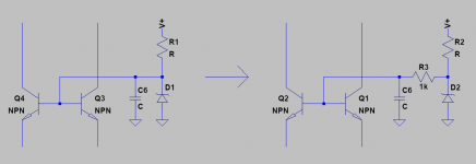
To stop any confusion (Tony) even though I made it clear in my original post that I was discussing the ZENER current - see simplified schematic attached for reference.
so, make a dedicated schematic to show, nothing can be simpler....
also a dedicated schematic for the resistor devider method....
Hi Harry, As it is unlikely that OS will chime in on this. One theory is that the circuit was designed first with the resistor option, so R19 and R18 were sized according to set the base voltage of the cascode to around 15v.
Are there any other theories as to how OS obtain a value of 68K?
actually the base voltage of the cascode Q3Q4 is set in order to get a certain collector voltage for the long tail pair trannies Q1Q2....
the voltage dividers where decided opun with the design assumption that the Hfe of the cascode tranies are greater than 100 or better...in such cases, one can simply assume that Ic equals Ie....so that the voltage appearing at the junction of the 68k and 22k is around 15 volts...15 volts is much much larger than the base emitter voltage of around 0.6 volts so that we just assume the collector voltage of the long tail pair is 15 volts.....
Last edited:
Page 19 here documents the skippy breakdown characteristics of zeners:
https://www.onsemi.com/pub/Collateral/HBD854-D.PDF
We don't know for sure this is causing the oscillation, but it is possible.
Another possibility is that the cascode is oscillating. What we know is that it goes away when removing C6.
So I propose the following modification. If it doesn't work, then move C6 to the other side of R3 and find a working value. If that is the case then it is likely the oscillation is caused by the cascode and not by the zener.
Attachments
@Stuart - what voltage rails does your HB have?
64v Rails.
so, make a dedicated schematic to show, nothing can be simpler....
also a dedicated schematic for the resistor devider method....
I have already posted part of the schematic, that some of the builders have an issue with. I have also described the issue in detail. It cannot be any simpler. Other members have understood and replied on this issue.
However none of your posts relate to the zener option that is in question.
Since the schematics need updating, as discussed many weeks ago, as a moderator you should know how to do that or what the process is, to change them.
Tony I will not continue to discuss this with you as it's counterproductive and focus will be on new builders who require guidance.
I used this zener from on semi. It is available at mouser.
512-1N4744ATR
This is a 1Watt zener.
Did you check with an oscilloscope if you have a oscillation at start up?
Hi Harry, I did not, not sure how to check for oscillation at start up. My one completed channel played music for about an hour yesterday in the garage. And sounds pretty good. Doesn't get hardly warm while playing.
Why would the watt rating of a zener cause oscillation? Up to 1 watt is called out as acceptable in the build guide. My understanding is limited, but improving. A zener should pass the correct voltage once the threshold voltage is passed, correct? So a 1/2w zener rated for 15v should pass the same voltage and current as a 1w zener rated for 15v? No? I am eager to learn.
I did have a problem with the other channel. I did something stupid, (not following directions) and I hooked it up without the heatsink, and with the fuses in place. I also had the bias resistor turned backwards, so it went to class a instead of class b. One output device on + and one on - popped, and the fuse popped. It also cause the r53 and 54 across the fuses to go out of spec. I tested all the other resistors and diodes, and they all check out. So I put 10 ohm 1w resistors in, and replaced the 22 ohm r53 and r54. (which I guess you only need one or the other). Removed the fuses, and put one output transistor in. Double checked all my trimmer resistors, and it looked pretty stable. Occasional fluctuation in DC offset voltage. Could this be oscillation caused? Was generally stable, but would occasionally fluctuate a few mv instead of totally stable. I hooked up a sine wave to the input, and after seeing a sine wave for a min, or so, (wave was not as clean as the good channel), r54 across the fuse lit up and smoked. So I checked all resistors again, and all others checked out. I am suspecting bad driver transistors, even though they measure out ok with no load. A few different transistors could fail, and lead to high current from the negative rail, I'm suspecting the driver transistors, but I am having a hard time finding differences in measurements between the bad channel and the good channel. Then I would suspect q11 or q12. So having trouble with fault finding.
Last edited:
You can purchase these off ebay.
PCB Print Circuit 10Pcs 0.6-1.5mm CNC Board Carbide Mini Micro Drill Bits SS0595 732040972633 | eBay
I just use them by hand stepping up one size at a time until the component fits.
View attachment 863412
I ordered some of those from Amazon. Broke 3 .6 bits on 2 vias. Putting this project aside for now.
Hi Summitp
This is a quick reply as I am not home and I'm using my phone.
A zener needs a certain minimum current to operate correctly. Generally speaking a 0.5Watt need less. See the links that Stuart posted for more info.
As for oscillation I use an oscilloscope to check however Stuart had a hissing sound at start up that faded. Perhaps your amp does not do that, as every build is different???
The resistors across the fuses are only used when turning on the amp for the first time, without the fuses in place. If they smoke you know that something is drawing too much current. Others use a light bulb in series with the mains voltage as a precaution.
The small dc offset fluctuation is normal.
Keep us posted on your progress.
Question regarding the suitable heatsink for the Honey Badger
Hello DIYers. I am in the process of building the Honey Badger amplifier and I want to select a chassis. I am building a dual mono PSU so I have 2 Universal PSU PCBs and 2 toroidal transformers (Φ~120mm).
I initially wanted to get the 4U Dissipante chassis with depth = 300mm but I realized that all the components don't fit comfortably inside. I can't get the 4U 400mm chassis because of budget reasons so I've ended up with the 3U 400mm chassis. My concern is whether its heatsinks are sufficient. This is my reasoning:
In the 4U 300mm chassis on diyaudiostore it is mentioned that it is suitable for the Honey Badger amp. Each one of its heatsinks is 0.31C/W.
On the other hand, each one of the 3U 400mm chassis' heatsinks is 0.5C/W. However, the 6 output semiconductors (that need the 0.31C/W to work comfortably) are split into 3 + 3 when installed in the 3U chassis, because it has 2 heatsinks in each side. If the 6 of them need 0.31C/W to work comfortably, the 3 of them need 2 * 0.31=0.62C/W, as they dissipate half the power. Because 0.62 < 0.5, I suppose that enough power will be dissipated to keep the output devices cool in the 3U chassis. Could you correct me if I'm wrong?
2 functioning channels. My idiocy that led to trouble, with a popped output transistor was due to not having the outputs on a heatsink, and having adjusted the pot for bias incorrectly. I had trouble fault finding, but found the fault last night, I was seeing very high DC offset. I yoinked the zener diode out of there and put r18 in. I didn't trust the drivers after the blown output, so I replaced them with a pair 2SC4793 / 2SA1837 from an old Yamaha. They seem to work fine. Amp fires up and idles. She is adjusted and is stable and produces a clean sine wave on the scope. Tomorrow is more testing, and then work on something else until the speaker protection board stuffings show up.
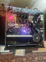
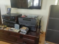
Honey badger cranking out tunes and shaking the house. To be done, add Vu meters, add power indicator led to front panel, add temperature control to fans.
It has lots of power, cranking the big bang and olufsens sounds great! Thanks Os for the design, and everyone for help getting it going. It's sweet!
It has lots of power, cranking the big bang and olufsens sounds great! Thanks Os for the design, and everyone for help getting it going. It's sweet!
Attachments
- Home
- Amplifiers
- Solid State
- diyAB Amp The "Honey Badger" build thread